| Issue |
EPJ Appl. Metamat.
Volume 13, 2026
|
|
|---|---|---|
| Article Number | 14 | |
| Number of page(s) | 11 | |
| DOI | https://doi.org/10.1051/epjam/2026005 | |
| Published online | 19 May 2026 | |
https://doi.org/10.1051/epjam/2026005
Original Article
High-efficiency terahertz third harmonic generation from quasi-bound states in the continuum in permittivity-asymmetric hybrid metasurface
1
Shaanxi Key Laboratory of Liquid Crystal Polymer Intelligent Display, Technological Institute of Materials & Energy Science (TIMES), School of Electronic Information, Xijing University, Xi’an 710123, PR China
2
Key Laboratory of Ultrafast Photoelectric Technology and Terahertz Science in Shaanxi, Xi’an University of Technology, Xi’an 710054, PR China
3
National Key Laboratory of Microwave Photonics (Tianyuan Laboratory), College of Electronic and Information Engineering, Nanjing University of Aeronautics and Astronautics, Nanjing 211100, PR China
4
Terahertz Research Center, School of Electronic Science and Engineering, University of Electronic Science and Technology of China, Chengdu 610054, PR China
* e-mail: This email address is being protected from spambots. You need JavaScript enabled to view it.
Received:
10
December
2025
Accepted:
13
April
2026
Published online: 19 May 2026
Abstract
Optical resonators with high quality (Q) factors are highly desirable in meta-optic and nanophotonic fields. Recently, bound states in the continuum (BIC) have emerged as a pivotal solution to enhance the Q factors of optical resonators to theoretically infinite values, leveraging non-dissipative energy confinement, specific resonance conditions, and destructive interference. However, in all-dielectric structures, the field distribution of BIC is predominantly confined within the metasurface (MS), posing significant challenges to the precise control of mode volume. Here, we propose a metal-dielectric hybrid MS that supports two symmetry-protected BIC, both of which are topologically protected by polarization vortices. Notably, the BIC mode volume is drastically reduced via coupling with surface plasmon polaritons, forming a hybrid mode with enhanced field localization. Specifically, we achieve high-efficiency terahertz third harmonic generation (THG) by breaking the dielectric constant symmetry of the structure to excite quasi-BIC. When the incident power of the fundamental frequency wave reaches 1 kW/cm2, the THG conversion efficiency peaks at an impressive 1.5%. Our findings not only provide a pathway for designing optical components with both high Q factors and low mode volumes but also offer a feasible strategy to boost nonlinear optical effect, opening new avenues for advanced nanophotonic applications.
Key words: Bound states in the continuum / terahertz metasurface / topological charge / nonlinear optical effect
© G. Sun et al., Published by EDP Sciences, 2026
 This is an Open Access article distributed under the terms of the Creative Commons Attribution License (https://creativecommons.org/licenses/by/4.0), which permits unrestricted use, distribution, and reproduction in any medium, provided the original work is properly cited.
1 Introduction
Frequency conversion stands as a foundational application in nonlinear optics, relying on robust light-matter interactions to enable efficient energy transfer across distinct frequency regimes [1–4]. However, when the dimensions of photonic structures shrink to the nanoscale—below the wavelength of incident light, conventional phase-matching techniques become ineffective at boosting conversion efficiency [1]. This limitation has spurred the pursuit of innovative strategies to advance nonlinear optical phenomena at the nanoscale. In recent years, metasurfaces (MSs) fabricated from high-refractive-index materials have emerged as a rapidly evolving platform for nonlinear photonics [3,5,6]. The high refractive index of these materials enables efficient confinement of electromagnetic fields within the structure, thereby enhancing the efficacy of nonlinear effects [7]. This approach holds significant promise for developing high-performance nanoscale nonlinear devices [2,3]. Nevertheless, the quality (Q) factors of traditional resonant modes excited in such MSs remain insufficient to foster strong light-matter interactions, resulting in relatively low overall efficiency of nonlinear processes.
The advent of bound states in the continuum (BIC) has introduced a transformative design paradigm for achieving ultra-high Q factor guided-mode resonances in the MSs [8–13]. BIC modes are characterized by their inability to dissipate energy to the exterior as plane waves, theoretically yielding infinite Q factors [14–17]. Based on their coupling mechanism with the radiative continuum, BIC are broadly categorized into symmetry-protected BIC (SP-BIC) and accidental BIC [18,19]. SP-BIC exclusively exist at high-symmetry points in momentum space, arising from symmetry mismatches in eigenmodes [20,21]. By breaking structural symmetry, SP-BIC can be transformed into quasi-BIC (QBIC) [22–26]. A slight deviation from the symmetric configuration allows QBIC to radiate electromagnetic energy into the external continuum, resulting in high Q factor resonances [27–30]. Consequently, QBIC-driven all-dielectric MSs exhibit substantial potential for applications in nonlinear enhancement [1,31], optical microcavities [32,33], nanolasers [34], and sensors [35,36].
Despite their ability to achieve ultrahigh Q factors, BIC suffer from relatively large mode volumes compared to small-volume modes such as plasmonic modes. In all-dielectric structures, the electromagnetic field of BIC is primarily confined within the MS volume, hindering effective local field enhancement and complicating the manipulation of optical properties [37,38]. In contrast, plasmonic modes offer significantly smaller mode volumes but suffer from intrinsic ohmic losses in metals, leading to low resonance Q factors that restrict their practical applications. Most importantly, inducing QBIC by modifying the geometric parameters of the MSs poses inherent challenges, as it is constrained by the limitations of state-of-the-art nanofabrication accuracy. Surface plasmon polaritons (SPPs) are collective electron oscillations propagating along the metal-dielectric interface, which exhibit strong field confinement and can be efficiently coupled with BIC modes in the MS. This coupling mechanism breaks the inherent trade-off between high Q factors and small mode volumes, enabling both strong field localization and efficient nonlinear light-matter interaction [39].
To surmount this obstacle, we propose a novel metal-dielectric hybrid MS capable of supporting resonances from two distinct modes governed by SP-BIC. Our results demonstrate that SP-BIC in specific modes can mutually excite and couple with SPPs, leading to strong localization of the electric field in the dielectric layer between the MS and the metal film. This coupling effectively reduces the optical mode volume while maintaining high Q factors—overcoming the trade-off between Q factor and mode volume observed in conventional structures. In addition, we also introduce a novel scheme to induce QBIC via dielectric constant perturbations in the MS. This approach enables ultra-small dielectric constant perturbations in silicon and other semiconductor materials through photogenerated free carrier injection, chemical doping, or electrooptical Pockels/Kerr effects—facilitating the realization of asymmetric parameter spaces that are geometrically unattainable. Simulations confirm that this method is fully equivalent to breaking geometric symmetry for QBIC excitation. Under QBIC resonance, we evaluate the performance of the dielectric constant-asymmetric hybrid MS as a nonlinear platform, achieving extremely high energy conversion efficiency for third-harmonic generation (THG) in the terahertz (THz) region. Compared to existing studies, our designed photonic platform substantially improves THG conversion efficiency in the THz regime. These findings underscore the potential of BIC resonances supported by high-refractive-index MSs and provide valuable insights for research and applications across diverse optical fields, laying the groundwork for a wide range of advanced nanophotonic technologies.
2 Metasurface design and simulation modeling
At the outset of this paper, we first elaborate on the structural model under investigation and the corresponding computational methodologies employed. The schematic illustration of the metal-dielectric hybrid MS herein is depicted in Figure 1a, while Figure 1b presents a cross-sectional view of a single unit cell within this periodic structure. The metal-dielectric hybrid system consists of an square-lattice array of silicon (Si) pillars deposited on a silver (Ag)/quartz (SiO2) multilayer substrate, with an SiO2 thin film acting as the spacer layer. In this work, the key structural parameters are defined as follows: a denotes the periodicity of the array, d represents the diameter of the Si pillars, h is the overall height of the structure, e is the thickness of the thin SiO2 spacer layer, and l is the thickness of the Ag layer. The thickness of the SiO2 substrate is denoted as w = 170 μm, which is sufficiently thick to eliminate substrate mode interference in the THz frequency range studied. The refractive indices of Si (nSi = 3.48), SiO2 (nquartz = 1.45) and air (nair = 1) are averaged values over the target THz regime. Material dispersion effects are negligible within this narrow frequency band, as confirmed by reference [31,40,41], which validates the use of constant refractive indices for simulation. For the Ag film, a constant electrical conductivity of 6.3 × 10⁷ S/m was assigned [3].
Based on the aforementioned material parameter models, we employ the finite element method-based simulation commercial software COMSOL MULTIPHYSICS to systematically investigate the light-matter interaction behaviors within the designed MS illustrated in Figure 1. Three-dimensional simulations were conducted via the eigenfrequency solver provided by COMSOL MULTIPHYSICS, which was employed to calculate key modal properties of the THz-MS, including band structures, mode profiles, Q factors, and polarization vectors in momentum space. For characterizing the optical performance, full-wave simulations based on the frequency-domain solver were utilized to obtain both the far-field optical response and electromagnetic near-field distributions of the THz-MS. Regarding multipole analysis, the far-field scattered power of Cartesian multipoles was computed by combining COMSOL MULTIPHYSICS simulations with an open-source MATLAB package dedicated to multipole expansion in nanophotonics applications [40]. We used coupled frequency-domain interfaces in COMSOL MULTIPHYSICS to simulate the THG from the proposed MSs. The third-order nonlinear susceptibility (χ(3)) was assigned to the nonlinear active layer (e.g., the Si microdisk), with a typical value of 2.45 × 10⁻¹⁹ m2/V2 calibrated to experimental references [3,31]. For THG simulation, two frequency-domain interfaces were configured: one for the fundamental frequency (FF, ω) and the other for the third harmonic (TH, 3ω). These two interfaces are coupled through polarization terms (P) incorporated into each interface, where the polarization for the FF interface is defined as P(ω) = 3χ(3)E(3ω)E*(ω), and that for the TH interface is set to P(3ω) = χ(3)E3(ω) [42]. The THG conversion efficiency was quantified as the ratio of the 3ω transmitted power (collected by the open port) to the fundamental input power, enabling quantitative evaluation of the nonlinear optical performance of the hybrid MS. In all simulations, periodic boundary conditions with Floquet periodicity were imposed along the x and y directions to mimic the infinite extensibility of the MS array, while perfectly matched layers (PMLs) were applied in the z direction to fully absorb outgoing scattered light and eliminate non-physical reflections. To ensure the eigenmodes exhibit transverse electric (TE)-like characteristics, a perfect magnetic conductor boundary condition was applied on the z = 0 plane (positioned at the midplane of the Si microdisk resonator). A normal-incident y-polarized THz wave was introduced into the MS through an air boundary via an open port placed beneath a PML; the same port was symmetrically positioned on the opposite side to collect the transmitted power. For convergence accuracy, the mesh size was uniformly set to less than one-fifth of the minimum wavelength in the simulation domain.
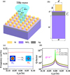 |
Fig. 1 (a) Schematic illustration of the metal-dielectric hybrid MS. (b) Front view of a single unit cell, with a unit cell period of a = 98 μm, Si pillar height h = 48 μm, SiO2 spacer layer thickness e = 7 μm, Ag layer thickness l = 25 μm, central cylinder diameter d = 50 μm, and SiO2 substrate thickness w = 170 μm. (c) Simulated two lowest-frequency TE-like band structure of the MS. The inset showing the electric field distribution (normE) of BIC mode at the Γ point. (d) Simulated radiation Q factors for the TE1 and TE2 bands in momentum space. The orange and green line represent fitted Q factor curve of the TE1 and the TE2 band, respectively. |
3 Results
3.1 Structural design and dispersion characteristics of SP-BIC
The structural characteristics and functional performance of the MSs are inherently governed by the resonant eigenmodes they sustain. In this work, we initiate our investigation by systematically calculating the eigenmodes supported by the designed MS. Based on the symmetry and field distribution properties, these eigenmodes can be categorized into two distinct types: a transverse magnetic (TM)-like mode and a TE-like mode. Specifically, for the TM-like mode, the z-component of the electric field (Ez) vanishes at the mirror plane along the z-direction (i.e., Ez = 0), while the TE-like mode is characterized by the absence of the z-component of the magnetic field (Hz) at the same mirror plane (i.e., Hz = 0). Here, we focus only on the two lowest-frequency TE-like modes that are above the light cone while below the diffraction limit, that is, the TE1 and TE2 modes. Figure 1c plots the simulated band diagram along the highly symmetrical M-Γ-X direction for two low-frequency TM-like modes. A comprehensive analysis of the band structures reveals that both the TE1 and TE2 bands exhibit quasi-flat-band dispersion behavior, indicating strong localization of the electromagnetic field. The inset in Figure 1c presents the electric field mode profiles (normE) of the two modes at the Γ point. According to group theory, the mode fields of the SP-BIC both belong to the irreducible representation A1 [10,43]. For structures with C4v symmetry, only non-degenerate modes exist at the Γ point, which gives rise to singlet BIC that are inherently polarization-related. Consequently, the two bands corresponding to SP-BIC are exclusively present in the TE bands and absent in the TM bands. Figure 1d depicts the relationship between the Q factors of the two bands and the wave vector in reciprocal space. At the high-symmetry Γ point, the Q factors of both modes approach infinity, confirming that each mode sustains a SP-BIC. The orange and green lines in Figure 1d represent the fitted Q factor curves. Notably, the Q factors exhibit an inverse square dependence on the wave vector, following the relation Q ∝ k−2.
3.2 Topological properties of SP-BIC
BIC are special electromagnetic eigenstates defined by infinite Q factors and zero resonance linewidth. While BIC transformed into QBIC with Fano line shapes are commonly used to identify BIC existence, numerical simulations may fail to distinguish true BIC from QBIC if the frequency or wavelength step is insufficiently small. The topological nature of BIC dictates that an ideal BIC must correspond to a vortex singularity in the far-field polarization direction. Thus, calculating and analyzing the topological properties of BIC is the most rigorous method to confirm the presence of true BIC [40–42]. To characterize the topological properties of the SP-BIC, we computed the two-dimensional polarization vector of the far-field in momentum space  [17,40]. The topological charge q carried by a BIC is defined as the winding number of the polarization vector around the BIC point, expressed as [14,18,41,44,45]:
 (1)
(1)
where  represents the angle between the major axis of the polarization ellipse and the x-axis, and L is a closed trajectory in momentum space that winding the vortex center in the counterclockwise direction. Here, Si denotes the Stokes parameters of C(k), with
  ,
,  ,
,  ,
,  [40,45,46]. If the closed loop L encloses a vortex singularity in the first Brillouin zone, the Stokes parameters S1, S2, and S3 are all zero, indicating that the BIC carries an integer topological charge.
To reveal the topological characteristics of the two SP-BIC, we calculated the far-field topological structure of the BIC. The color maps in Figures 2a and 2b demonstrate the presence of SP-BIC at the center of the Brillouin zone on the TE1 and TE2 bands, respectively. The calculated far-field polarization vector distribution in Figures 2c and 2d indicates the formation of vector polarization singularities at the BIC locations. Owing to topological charge conservation, these BIC are stable and correspond to the intersection points of the node lines Cx = 0 (red lines) and Cy = 0 (green lines), as shown in Figures 2c and 2d. In momentum space, these intersection points are regions where the polarization vector vanishes, and BIC reside precisely at these positions. The properties and topological charge of the BIC can be further identified by the intersection points and the signs of the polarization directions Cx and Cy. As shown in Figures 2c and 2d, when the polarization vector rotates by 2π along a closed loop surrounding the BIC point in momentum space, the topological charge is determined to be q = +1. Within the wave vector range ∣k∣ = 0.1, the magnitude of S3 is extremely small (–0.05 to 0.05), leading to approximately linear polarization of C(k), as illustrated in Figures 2e and 2f. These results confirm the topological protection of the SP-BIC, ensuring their stability and robustness against structural perturbations.
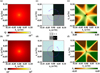 |
Fig. 2 (a, b) 2D Q factor maps for the TE1 and TE2 bands. The color hues denote the Q factors of the eigenmodes. (c, d) Polarization vector distributions of the TE1 and TE2 eigenmodes that showcases a topological charge of q = 1. The red line represents Cx = 0, the green line represents Cy = 0, the cyan arrows indicate the direction of the polarization vector, and the purple ring shows the variation trend of the polarization vector direction. (e, f) Stokes parameter S3 distributions of the TE1 and TE2 modes |
3.3 Symmetry breaking and high-Q QBIC excitation
To gain a more intuitive understanding of SP-BIC, we transformer the ideal BIC without resonance peaks into QBIC with sharp resonance peaks by broking the momentum-space symmetry of the THz-MS [9,31]. Instead of modifying the structural geometric parameters, we adjusted the incident angle θ of electromagnetic waves to disrupt the symmetry. We analyzed the reflectivity spectra of the MS for incident angles θ ranging from −8° to +8° to investigate the effect of incident angle on reflectivity. Figure 3a presents a color map of the relationship between reflectivity, frequency, and incident angle. As observed in Figure 3a, with an increase in ∣θ∣, the resonance frequency of the TE2 mode undergoes a blue shift, while the TE1 mode exhibits a red shift. Additionally, the linewidth of both modes broadens with increasing ∣θ∣, indicating the transformation of resonance from SP-BIC to QBIC with finite Q factors. Notably, there is strong mode coupling between the SP-BIC of the TE2 mode and SPPs. To verify the advantages of the hybrid structure, we calculated the Q factors of a plasmonic structure (Si pillars directly placed on a Ag layer) in the same mode and compared them with those of the hybrid structure. The results, shown in Figure 3b, demonstrate that the hybrid structure achieves significantly higher Q factors than the plasmonic structure, highlighting the superior performance of the proposed hybrid design. We further compared the electric field distributions of the hybrid MS and a conventional all-dielectric MS. Figures 3c and 3d display the electric field distributions of BIC in the x-z plane for the hybrid and all-dielectric MS, respectively, under the TE2 mode. For the all-dielectric MS, the electric field is primarily confined within the MS volume. In contrast, for the hybrid MS, the electric field is strongly localized within the SiO2 spacer layer due to the coupling between SPPs and the BIC mode, which significantly reduces the optical mode volume of the BIC. Furthermore, the optical mode volume of the BIC can be arbitrarily adjusted by varying the thickness of the SiO2 spacer layer. It is important to note that due to inherent metallic losses, the field enhancement factor of the SPP-coupled BIC in the hybrid structure is slightly weaker than that of the all-dielectric BIC.
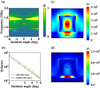 |
Fig. 3 (a) 2D color map of reflectivity as a function of frequency and incident angle. Pink and red circles indicate the positions of SP-BIC, and purple points represent SPPs. (b) Q factors of QBIC as a function of incident angle for the hybrid structure (green) and the plasmonic structure (red). (c) Electric field distribution of the BIC in the x-z plane under the TE1 mode in the hybrid THz-MS. (d) Electric field distribution of the BIC in the x-z plane under the TE2 mode in the hybrid THz-MS. |
3.4 The physical origin of BIC resonance
To gain deeper insights into the resonance mechanism of QBIC on the TE1 mode, we decomposed the far-field radiation of the QBIC into contributions from five multipole components in the Cartesian coordinate system: electric dipole (ED), magnetic dipole (MD), electric quadrupole (EQ), magnetic quadrupole (MQ), and toroidal dipole (TD). Higher-order terms in the multipole expansion were neglected due to their negligible contribution. The multipole moment expansion was performed by integrating the induced displacement current density j(r) over the unit cell of the MS. Accordingly, the induced Cartesian multipole moments in free space are expressed as follows [3,31,47,48]:
 (2)
(2)
 (3)
(3)
 (4)
(4)
 (5)
(5)
 (6)
(6)
Here ω denotes the angular frequency corresponding to the resonant state; c represents the speed of light in vacuum; r specifies the spatial position at which the induced displacement current density j is evaluated; and α, β ∈ {x, y, z}, where x, y, z correspond to the Cartesian coordinate components. The far-field scattering power of the corresponding multipole moments is expressed as follows [47,48]:
 (7)
(7)
 (8)
(8)
 (9)
(9)
 (10)
(10)
 (11)
(11)
The total scattering power contribute to the far-field response can therefore be calculated by the following formulas:
 (12)
(12)
Here, we study the resonant properties and corresponding scattering powers of the QBIC mode with θ = 2° as an example, as shown in Figure 4a. The multipolar decomposition result reveals that the MD component dominates the far-field radiation of the TE1 QBIC mode, while the contributions from ED, MQ, EQ, and TD are significantly suppressed. A detailed analysis of the x, y, and z components of the MD scattering power demonstrates that the z component is dominant at the resonance peak, with a value nearly equal to the total MD scattering power, as shown in Figure 4b. In contrast, the x and y components of the MD scattering power are almost negligible at the resonance peak, approaching zero. This indicates that the MD moment of the QBIC mode is primarily oriented along the z direction. We also analyse the electric and magnetic field distributions of MD quasi-BIC mode at different top or lateral cross-sectional views to verify this inference. Figures 4c and 4d display the magnetic field Hz distribution and electric field vectors in the x-y plane, and the electric field Ey distribution and magnetic field vectors in the x-z plane, respectively. In the x-y plane, the electric field forms a vortex, representing a typical signature of MD resonance. In the x-z plane, the magnetic field vectors form clockwise and counterclockwise vortices on the left and right sides of the z-axis, respectively. The presence of these magnetic field loops further confirms the MD resonance nature of the TE1 mode. The unique optical field enhancement mechanism of ultrahigh-Q MD QBIC can immediately bring promising applications in nonlinear frequency conversion, which will be demonstrated next.
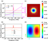 |
Fig. 4 (a) Reflection spectra and multipole decomposition of scattering power for the TE1 band. (b) Scattering power of the MD components. (c) Magnetic field Hz distribution and electric field vectors in the x-y plane for the TE1 mode. (d) Electric field Ey distribution and magnetic field vectors in the x-z plane for the TE1 mode. |
3.4 Enhanced third harmonic generation under QBIC resonance
To demonstrate the nonlinear optical response boosted by the robust high-Q MD-BIC, we performed THG simulation calculations based on the proposed metal-dielectric hybrid MS using the coupled electromagnetic waves interface in COMSOL MULTIPHYSICS. We first simulate the linear optical response at the FF to map the spatial distribution of the linear electric field. Using this linear field E(ω), we then compute the third-order nonlinear polarization induced within the THz-MS, from which the nonlinear polarization at the TH is subsequently derived [3,31].
 (13)
(13)
Figure 5a schematically illustrates the THG process via direct nonlinear optical process. We perturbed the dielectric constant of a 60° sector on the right side of the Si pillar while keeping the dielectric constant of the remaining parts unchanged. This method is fully equivalent to breaking geometric symmetry while preserving the ideal geometric shape of the MS. We defined a dimensionless asymmetry parameter α = Δε/εSi to describe the degree of dielectric constant asymmetry, where Δε is the variation in dielectric constant and εSi is the original dielectric constant of Si microdisk. The THG conversion efficiency is defined as ηTHG = PTHG/PFF, where PTHG is the radiated power at the TH frequency and PFF is the incident power of the FF wave. Figure 5b shows the reflection spectrum and the relationship between ηTHG and the pump light frequency near the QBIC resonance. The THG conversion efficiency spans 11 orders of magnitude, with the maximum efficiency occurring at the QBIC resonance frequency. A distinct emission peak at 4.6774 THz is observed when the pump frequency is fixed at 1.55913 THz, providing unequivocal evidence of frequency-tripled photon generation. Even when the incident FF intensity is as low as I0 =1 kW/cm2, the peak THG conversion efficiency reaches approximately 1.5%, which is significantly higher than the efficiencies reported in previous studies [3,31,49-51]. Figures 5c and 5d depict the FF and normalized TH electric field distributions at the QBIC resonance frequency, respectively. The FF electric field is uniformly distributed within the THz-MS, with a very strong field enhancement in the vicinity of the QBIC resonance. The field enhancement factor (∼230) is defined as the ratio of the maximum local electric field intensity (|E(ω)|2) at the QBIC resonance frequency to the incident electric field intensity (|Eint(ω)|2) in the absence of the MS. This quantification is based on the finite element method simulation results, where the incident wave is a linearly polarized plane wave with a power density of 1 kW/cm2, consistent with the experimental pump conditions. In contrast, the TH electric field is more delocalized, with a very weak field enhancement factor, indicating almost all the electromagnetic energy stored in the MS at the FF frequency is utilized to drive the TH nonlinear process.
We further investigated the dependence of THG power on the pump light polarization angle, as shown in Figure 5e. We find that THG intensity is highly sensitive to the pump light polarization angle. When the pump light polarization angle is orthogonal to the TE wave polarization angle (0° or 180°), the THG intensity is minimized, while the maximum THG intensity is 1013 times higher than the minimum value. This strong polarization dependence provides a means to dynamically tune the THG output by adjusting the pump light polarization. In order to further verify the TH nonlinear optical effect in the THz-MS, we calculated the dependence of the THG generation power on the FF pump power. Figure 5f presents the double-logarithmic relationship between THG power and FF pump power. When the FF pump power approaches 0.6 W, the peak THG power reaches 0.35 W. A curve fitting analysis reveals that PTHG is proportional to the cube of PFF ( ), which is consistent with the TH nonlinear nature of the THG process, providing direct evidence for the validity of the observed THG phenomenon. The concurrent enhancements of THG and light-matter interaction efficiency unequivocally demonstrate the tremendous potential of our proposed permittivity-broken QBIC metal-dielectric hybrid THz-MS for advancing THz nonlinear photonics.
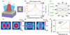 |
Fig. 5 (a) Schematic illustration of dielectric constant perturbation and enhanced THG. (b, c) The electric field distributions of the FF and TH on the unit cell cross-section under QBIC resonance frequency. (c) Relationship between the reflection spectrum and THG conversion efficiency as a function of pump light frequency near the QBIC resonance frequency. (e) The dependence of THG power on the polarization angle of pump light. (f) The double-logarithmic plot of THG power versus FF pump power. The fitting curve confirming the cubic relationship of TH optical effect. |
4 Conclusion
In summary, we have proposed a metal-dielectric hybrid THz-MS based on a square lattice of Si cylinders and demonstrated that it can support two SP-BIC on the two lowest-frequency TE-like band. Our key findings reveal that SP-BIC in specific modes can strong couple with SPPs originating from the metal Ag film, leading to a significant reduction in the optical mode volume and strong localization of the electric field within the SiO2 spacer layer between the Si pillars and the Ag film. This coupling mechanism overcomes the inherent trade-off between Q factor and mode volume in conventional all-dielectric nanostructures, enabling the realization of optical components with both ultra-high Q factors and low mode volumes. Furthermore, for the metal-dielectric hybrid MS with a dielectric constant asymmetry parameter of 0.01, we achieved a record-high THG conversion efficiency as high as 1.5% at a relatively low pump intensity of 1 kW/cm2 in the THz region. This super performance is attributed to the strong light-matter interaction enhanced by QBIC resonance and the novel dielectric constant perturbation method, which avoids the fabrication challenges associated with geometric symmetry breaking. The proposed hybrid THz-MS offers unique capabilities for manipulating BIC modes and achieving high-efficiency THG at low pump intensities. Our findings open up new opportunities for a wide range of nanophotonic applications, including low-threshold nano-lasers, ultra-sensitive biochemical sensors, and high-efficiency nonlinear THz sources. This work not only advances the fundamental understanding of BIC resonance modes in hybrid structures but also provides a practical platform for bridging the gap in high-efficiency THz nonlinear optics.
Funding
The authors acknowledge the research funding support from High-Level Talent Special Fund of Xijing University (XJ25B17), the National Natural Science Foundation of China (62275215, 62435015), the Key Core Technology Research Project for Strategic Industry Chains of Xi’an Science and Technology Bureau (23LLRH0057), and Natural Science Basic Research Program of Shaanxi Province (2024JCYBMS-408, 2025JC-YBMS-074).
Conflicts of interest
The authors have no conflicts to disclose.
Data availability statement
The data that support the findings of this study are available from the corresponding author upon reasonable request.
Author contribution statement
G.S. and Y.W. conceived the research idea, performed the theoretical analysis and numerical calculations, and drafted the paper. R.W., Y.L., G.B., Y.Z. and J.H. analyzed the data. G.S., Y.W., Y.Z., S.C., H.H. and S.H. supervised the project, and reviewed and edited the paper. All authors contributed with discussions on the analytic model, the results and writing the final version of the manuscript.
References
- L. Kang, Y. Wu, X. Ma, S. Lan, D.H. Werner, High-harmonic optical vortex generation from photonic bound states in the continuum, Adv. Opt. Mater. 10, 2101497 (2022), https://doi.org/10.1002/adom.202101497 [Google Scholar]
- L. Carletti, S.S. Kruk, A.A. Bogdanov, C.D. Angelis, Y. Kivshar, High-harmonic generation at the nanoscale boosted by bound states in the continuum, Phys. Rev. Res. 1, 023016 (2019), https://doi.org/10.1103/physrevresearch.1.023016 [Google Scholar]
- G. Sun, Y. Wang, R. Xie, X. Zhao, Polarization-insensitive terahertz third-harmonic generation from degenerate pairs of mirror-coupled super-BIC, Appl. Phys. Lett. 125, 081702 (2024), https://doi.org/10.1063/5.0221133 [Google Scholar]
- H. Zhao, Efficient second-harmonic generation in 3D colloidal crystals, Nat. Photonics 19, 7 (2025), https://doi.org/10.1038/s41566-024-01598-6 [Google Scholar]
- Y. Luan, A. Zilli, A.D. Francescantonio, V. Vinel, P. Biagioni, L. Duò, A. Lemaître, G. Leo, M. Celebrano, M. Finazzi, All-optical polarization encoding and modulation by nonlinear interferometry at the nanoscale, Light: Sci. Appl. 14, 318 (2025), https://doi.org/10.1038/s41377-025-01948-1 [Google Scholar]
- H. Qiu, X. Tu, M. Qin, F. Wu, T. Liu, S. Xiao, Electro-optically tunable second-harmonic generation in lithium niobate metasurfaces boosted by Brillouin zone folding induced bound states in the continuum, Phys. Rev. B 112, 085418 (2025), https://doi.org/10.1103/rq6f-qj5q [Google Scholar]
- X. He, M. Wu, G. Lu, Y. Zhang, Z. Geng, High-efficiency multi-channel focusing and imaging enabled by polarization-frequency multiplexing non-interleaved metasurfaces, Photonics Res. 13, 976 (2025), https://doi.org/10.1364/PRJ.545173 [Google Scholar]
- L. Wang, H. Liu, J. Liu, A. Liu, J. Huang, Q. Li, H. Dai, C. Zhang, J. Wu, K. Fan, H. Wang, B. Jin, J. Chen, P. Wu, Photoswitchable exceptional points derived from bound states in the continuum, Light: Sci. Appl. 14, 377 (2025), https://doi.org/10.1038/s41377-025-02036-0 [Google Scholar]
- S.C. Malek, T. Norden, C.F. Doiron, T. Santiago-Cruz, J. Yu, A. Cerjan, P. Padmanabhan, I. Brener, Giant enhancement of four-wave mixing by doubly zone-folded nonlocal metasurfaces, ACS Nano. 19, 35609 (2025), https://doi.org/10.1021/acsnano.5c10747 [Google Scholar]
- X. He, W. Cao, F. Lin, Tunable BIC metamaterials with Dirac semimetals, Nanophotonics 14, 4875 (2025), https://doi.org/10.1515/nanoph-2025-0358 [Google Scholar]
- W. Adi, S. Rosas, A. Beisenova, S.K. Biswas, H. Mei, D.A. Czaplewski, F. Yesilkoy, Trapping light in air with membrane metasurfaces for vibrational strong coupling, Nat. Commun. 15, 10049 (2024), https://doi.org/10.1038/s41467-024-54284-0 [Google Scholar]
- L. Huang, L. Xu, M. Rahmani, D. Neshev, A.E. Miroshnichenko, Pushing the limit of high-Q mode of a single dielectric nanocavity, Adv. Photonics. 3, 016004 (2021), https://doi.org/10.1117/1.AP.3.1.016004 [Google Scholar]
- A.C. Overvig, S.C. Malek, M.J. Carter, S. Shrestha, N. Yu, Selection rules for quasibound states in the continuum, Phys. Rev. B 102, 035434 (2020), https://doi.org/10.1103/PhysRevB.102.035434 [Google Scholar]
- L. Huang, A.E. Miroshnichenko, Evolution of topological polarization singularity in a photonic crystal slab, Laser Photonics Rev. 19, e00555 (2025), https://doi.org/10.1002/lpor.202500555 [Google Scholar]
- L. Rao, J. Wang, X. Wang, S. Wu, X. Zhao, W. Liu, R. Xie, Y. Shen, L. Shi, J. Zi, Meron spin textures in momentum space spawning from bound states in the continuum, Phys. Rev. Lett. 135, 026203 (2025), https://doi.org/10.1103/3g3j-mnh9 [Google Scholar]
- H. Zhong, L. Huang, S. Li, C. Zhou, S. You, L. Li, Y. Cheng, A.E. Miroshnichenko, Toroidal dipole bound states in the continuum in asymmetric dimer metasurfaces, Appl. Phys. Rev. 11, 031404 (2024), https://doi.org/10.1063/5.0200778 [Google Scholar]
- J. Li, Q. Duan, X. Dong, Z. Yang, Y. Hu, J. Zhi, S. Zhu, H. Chen, Chiral quasi-bound states in the continuum via Brillouin zone folding, Appl. Phys. Lett. 126, 241702 (2025), https://doi.org/10.1063/5.0269369 [Google Scholar]
- H. Zuo, S. Xia, H. Meng, Janus bound states in the continuum in structurally symmetric photonic crystals, Phys. Rev. B 112, 145414 (2025), https://doi.org/10.1103/s2zt-bbvn [Google Scholar]
- Y.X. Zhang, Q. Lin., X.Q. Yan, L.L. Wang, G.D. Liu, Flat-band Friedrich-Wintgen bound states in the continuum based on borophene metamaterials, Opt. Express 32, 10669 (2024), https://doi.org/10.1364/OE.515152 [Google Scholar]
- Y. Liang, D.P. Tsai, Y. Kivshar, From local to nonlocal high-Q plasmonic metasurfaces, Phys. Rev. Lett. 133, 053801 (2024), https://doi.org/10.1103/PhysRevLett.133.053801 [Google Scholar]
- R. Zhang, X.C. Li, Q.H. Liu, Tunable magneto-optical accidental bound states in the continuum with intrinsic chirality and nonreciprocal transmission, Phys. Rev. B 112, 014417 (2025), https://doi.org/10.1103/zgm2-nh53 [Google Scholar]
- Y. Zeng, X. Sha, C. Zhang, Y. Zhang, H. Deng, H. Lu, G. Qu, S. Xiao, S. Yu, Y. Kivshar, Q. Song, Metalasers with arbitrarily shaped wavefront, Nature 643, 1240 (2025), https://doi.org/10.1038/s41586-025-09275-6 [Google Scholar]
- J. Zhou, Z. Gong, M. Liu, B. Wang, C. Zhao, Ultranarrow and angle-insensitive thermal emitters enabled by quasi-bound states in the continuum with lattice perturbation, Nano Lett. 25, 14938 (2025), https://doi.org/10.1021/acs.nanolett.5c03588 [Google Scholar]
- N. Rozman, K. Fan, W.J. Padilla, Symmetry-broken high-Q terahertz quasi-bound states in the continuum, ACS Photonics 11, 1893 (2024), https://doi.org/10.1021/acsphotonics.3c01848 [Google Scholar]
- J. Fan, Y. Zhou, Z. Xue, G. Xu, J. Chen, H. Xing, D. Lu, L. Cong, Active singularity metadevices enabled by bound states in the continuum, Laser Photonics Rev. 19, 2401869 (2025), https://doi.org/10.1002/lpor.202401869 [Google Scholar]
- W.W. Wong, X. Huang, O. Lem, C. Jagadish, H.H. Tan, Near-unity spontaneous emission factor InP surface-emitting lasers based on quasi-bound states in the continuum, Sci. Adv. 11, eadx652 (2025), https://doi.org/10.1126/sciadv.adx652 [Google Scholar]
- S. Li, L. Huang, H. Zhong, M. Ning, L.E. Zhang, Y. Yin, Y. Cheng, L. Li, Observation of multiple quasi-bound states in the continuum by symmetry breaking in a photonic crystal slab, Photonics Res. 13, 968 (2025), https://doi.org/10.1364/PRJ.547681 [Google Scholar]
- G. Crotti, A. Schirato, O. Pashina, O. Sergaeva, M. Petrov, C.D. Angelis, G.D. Valle, Ultrafast switching of a metasurface quasi-bound state in the continuum via transient optical symmetry breaking, Light: Sci. Appl. 14, 240 (2025), https://doi.org/10.1038/s41377-025-01885-z [Google Scholar]
- H.C. Mo, W.J. Zhang, Z.Y. Wu, X.D. Chen, J. Dong, Brillouin zone folding induced spin–orbit-locking chiral BIC and quasi-BIC, ACS Photonics 12, 2795 (2025), https://doi.org/10.1021/acsphotonics.5c00377 [Google Scholar]
- H. Bai, A. Shevchenko, R. Kolkowski, Recovery of topologically robust merging bound states in the continuum in photonic structures with broken symmetry, Nanophotonics 14, 899 (2025), https://doi.org/10.1515/nanoph-2024-0609 [Google Scholar]
- G. Sun, Y. Wang, Z. Cui, R. Xie, X. Zhao, Enhanced terahertz high-harmonic generation from high-Q quasi-bound states in the continuum empowered by permittivity-broken metasurface, Appl. Phys. Lett. 124, 111704 (2024), https://doi.org/10.1063/5.0196849 [Google Scholar]
- R. Jin, X. Zhang, P. Huo, Z. Cai, Y. Lu, T. Xu, Y. Liu, Harnessing enantioselective optical forces by quasibound states in the continuum, Phys. Rev. Lett. 133, 086901 (2024), https://doi.org/10.1103/PhysRevLett.133.086901 [Google Scholar]
- T. Weber, L. Kühner, L. Sortino, A.B. Mhenni, N.P. Wilson, J. Kühne, J.J. Finley, S.A. Maier, A. Tittl, Intrinsic strong light-matter coupling with self-hybridized bound states in the continuum in van der Waals metasurfaces, Nat. Mater. 22, 970 (2023), https://doi.org/10.1038/s41563-023-01580-7 [Google Scholar]
- Z. Xu, Y. Liu, S. Chang, Q. Chang, B. Chen, C. Zhao, M. Sun, X. Gao, Y. Yan, T. Zhai, Ultrathin deployable femtosecond vortex laser, Adv. Mater. 37, 2507122 (2025), https://doi.org/10.1002/adma.202507122 [Google Scholar]
- J.A. Alvarez-Sanchis, B. Vidal, S.A. Tretyakov, A. Díaz-Rubio, Loss-induced performance limits of all-dielectric metasurfaces for terahertz sensing, Phys. Rev. Appl. 19, 014009 (2023), https://doi.org/10.1103/PhysRevApplied.19.014009 [Google Scholar]
- R. Wang, L. Song, H. Ruan, Q. Yang, X. Yang, X. Zhang, R. Jiang, X. Shi, A.P. Shkurinov, Ultrasensitive terahertz label-free metasensors enabled by quasi-bound states in the continuum, Research 7, 0483 (2024), https://doi.org/10.34133/research.0483 [Google Scholar]
- X. Xiao, Y. Lu, J. Jiang, Y. Chen, Manipulation of optical bound states in the continuum in a metal-dielectric hybrid nanostructure, Photonics Res. 10, 2526 (2022), https://doi.org/10.1364/PRJ.465119 [Google Scholar]
- J. Xiang, Y. Xu, J.D. Chen, S. Lan, Tailoring the spatial localization of bound state in the continuum in plasmonic-dielectric hybrid system, Nanophotonics 9, 133 (2020), https://doi.org/10.1515/nanoph-2019-0341 [Google Scholar]
- M. Wu, X. He, G. Lu, Y. Zhang, Z. Geng, H. Liu, K. Zhang, On-chip multi-channel wavefront manipulation of spoof surface waves with structural heterogeneous metasurfaces, Laser Photonics Rev. 20, e01634 (2025), https://doi.org/10.1002/lpor.202501634 [Google Scholar]
- G. Sun, Y. Wang, Y. Li, Z. Cui, W. Chen, K. Zhang, Tailoring topological nature of merging bound states in the continuum by manipulating structure symmetry of the all-dielectric metasurface, Phys. Rev. B 109, 035406 (2024), https://doi.org/10.1103/PhysRevB.109.035406 [Google Scholar]
- Y. Wang, G. Sun, W. Chen, X. Zhang, Y. Li, K. Fan, Z. Cui, Z. You, X. Zhao, Unlocking the Q-factor limit of topologically protected photonic bound states in the continuum in all-dielectric terahertz metasurfaces, Phys. Rev. Appl. 24, 014039 (2025), https://doi.org/10.1103/3r2g-8xxt [Google Scholar]
- Q. Liu, L. Qu, Z. Gu, D. Zhang, W. Wu, W. Cai, M. Ren, J. Xu, Boosting second harmonic generation by merging bound states in the continuum, Phys. Rev. B 107, 245408 (2023), https://doi.org/10.1103/PhysRevB.107.245408 [Google Scholar]
- J. Wang, P. Li, X. Zhao, Z. Qian, X. Wang, F. Wang, X. Zhou, D. Han, C. Peng, L. Shi, J. Zi, Optical bound states in the continuum in periodic structures: mechanisms, effects, and applications, Photonics Insights 3, R01 (2024), https://doi.org/10.3788/PI.2024.R01 [Google Scholar]
- X. Zhao, J. Wang, W. Liu, Z. Che, X. Wang, C.T. Chan, L. Shi, J. Zi, Spin-orbit-locking chiral bound states in the continuum, Phys. Rev. Lett. 133, 036201 (2024), https://doi.org/10.1103/PhysRevLett.133.036201 [Google Scholar]
- X. Zhang, J.P. Xu, Z.B. Zhang, Z. Zhu, Jumping and merging of bound states in the continuum on degenerate bands, ACS Photonics 11, 4251 (2024), https://doi.org/10.1021/acsphotonics.4c01164 [Google Scholar]
- S. Han, J. Cui, Y. Chua, Y. Zeng, L. Hu, M. Dai, F. Wang, F. Sun, S. Zhu, L. Li, A.G. Davies, E.H. Linfield, C.S. Tan, Y. Kivshar, Q.J. Wang, Electrically-pumped compact topological bulk lasers driven by band-inverted bound states in the continuum, Light: Sci. Appl. 12, 145 (2023), https://doi.org/10.1038/s41377-023-01200-8 [Google Scholar]
- S. You, M. Zhou, L. Xu, D. Chen, M. Fan, J. Huang, W. Ma, S. Luo, M. Rahmani, C. Zhou, A.E. Miroshnichenko, L. Huang, Quasi-bound states in the continuum with a stable resonance wavelength in dimer dielectric metasurfaces, Nanophotonics 12, 2051 (2023), https://doi.org/10.1515/nanoph-2023-0166 [Google Scholar]
- G. Sun, Y. Wang, R. Xie, X. Chen, Y. Li, W. Chen, K. Fan, Z. Cui, X. Zhao, Pushing Q-factor limit of guided resonances by harnessing topologically protected terahertz bound states in the continuum, Appl. Phys. Rev. 12, 011422 (2025), https://doi.org/10.1063/5.0254576 [Google Scholar]
- B. Wang, J. Liu, J. Liu, J. Liu, J. Liu, W. Sun, L. Li, Enhanced terahertz third-harmonic generation in graphene–metal metasurface with bound states in the continuum, J. Appl. Phys. 133, 023103 (2023), https://doi.org/10.1063/5.0132059 [Google Scholar]
- R. Degl’Innocenti, Y. Lu, A.M. Zaman, J.M. Woolley, N. Chopra, W. Tadbier, W. Michailow, S. Hofmann, J. Lloyd-Hughes, Terahertz harmonic generation and nonlinear spectroscopy of metamaterial-gated/graphene resonators, APL Photonics 10, 056101 (2025), https://doi.org/10.1063/5.0264305 [Google Scholar]
- C. Wang, Y. Tan, Y. Wen, S. Zhao, K. Yu, J. Sun, J. Zhou, Nonperturbative nonlinear metasurfaces for efficient terahertz harmonic generation, ACS Photonics 11, 1236 (2024), https://doi.org/10.1021/acsphotonics.3c01762 [Google Scholar]
Cite this article as: Guangcheng Sun, Rui Wu, Yaohe Li, Gengyu Bai, Yongming Zhang, Suguo Chen, Sunchao Huang, Yang Zhao, Jiayong Han, Hui Hu, Yue Wang, High-efficiency terahertz third harmonic generation from quasi-bound states in the continuum in permittivity-asymmetric hybrid metasurface, EPJ Appl. Metamat. 13, 14 (2026), https://doi.org/10.1051/epjam/2026005
All Figures
|
Fig. 1 (a) Schematic illustration of the metal-dielectric hybrid MS. (b) Front view of a single unit cell, with a unit cell period of a = 98 μm, Si pillar height h = 48 μm, SiO2 spacer layer thickness e = 7 μm, Ag layer thickness l = 25 μm, central cylinder diameter d = 50 μm, and SiO2 substrate thickness w = 170 μm. (c) Simulated two lowest-frequency TE-like band structure of the MS. The inset showing the electric field distribution (normE) of BIC mode at the Γ point. (d) Simulated radiation Q factors for the TE1 and TE2 bands in momentum space. The orange and green line represent fitted Q factor curve of the TE1 and the TE2 band, respectively. |
| In the text | |
|
Fig. 2 (a, b) 2D Q factor maps for the TE1 and TE2 bands. The color hues denote the Q factors of the eigenmodes. (c, d) Polarization vector distributions of the TE1 and TE2 eigenmodes that showcases a topological charge of q = 1. The red line represents Cx = 0, the green line represents Cy = 0, the cyan arrows indicate the direction of the polarization vector, and the purple ring shows the variation trend of the polarization vector direction. (e, f) Stokes parameter S3 distributions of the TE1 and TE2 modes |
| In the text | |
|
Fig. 3 (a) 2D color map of reflectivity as a function of frequency and incident angle. Pink and red circles indicate the positions of SP-BIC, and purple points represent SPPs. (b) Q factors of QBIC as a function of incident angle for the hybrid structure (green) and the plasmonic structure (red). (c) Electric field distribution of the BIC in the x-z plane under the TE1 mode in the hybrid THz-MS. (d) Electric field distribution of the BIC in the x-z plane under the TE2 mode in the hybrid THz-MS. |
| In the text | |
|
Fig. 4 (a) Reflection spectra and multipole decomposition of scattering power for the TE1 band. (b) Scattering power of the MD components. (c) Magnetic field Hz distribution and electric field vectors in the x-y plane for the TE1 mode. (d) Electric field Ey distribution and magnetic field vectors in the x-z plane for the TE1 mode. |
| In the text | |
|
Fig. 5 (a) Schematic illustration of dielectric constant perturbation and enhanced THG. (b, c) The electric field distributions of the FF and TH on the unit cell cross-section under QBIC resonance frequency. (c) Relationship between the reflection spectrum and THG conversion efficiency as a function of pump light frequency near the QBIC resonance frequency. (e) The dependence of THG power on the polarization angle of pump light. (f) The double-logarithmic plot of THG power versus FF pump power. The fitting curve confirming the cubic relationship of TH optical effect. |
| In the text | |
Current usage metrics show cumulative count of Article Views (full-text article views including HTML views, PDF and ePub downloads, according to the available data) and Abstracts Views on Vision4Press platform.
Data correspond to usage on the plateform after 2015. The current usage metrics is available 48-96 hours after online publication and is updated daily on week days.
Initial download of the metrics may take a while.