Fig. 2
Download original image
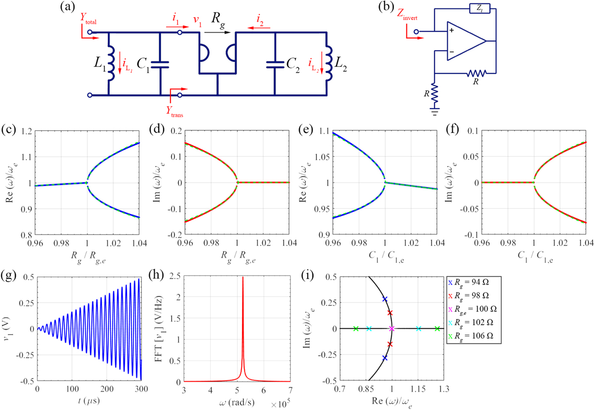
(a) The gyrator-based circuit with the ideal gyrator connected two parallel LC tanks. (b) Opamp-based circuit configuration to obtain negative inductance and capacitance. The sensitivity of the (c), (e), real and (d), (f), imaginary parts of the eigenfrequencies to (c), (d) gyration resistance, (e), (f) positive capacitance C1. Solid lines: solution of eigenvalue problem of Eq. (2); green-dashed lines: Puiseux series approximation truncated to its second term. Voltage of positive capacitance v1 (t) at EPD (g) time-domain, and (h) frequency-domain. The frequency-domain result is calculated by applying an FFT with 106 samples in the time window of 0 to 3 ms. (i) Root locus of zeros of Ytotal (ω) = 0 showing the real versus imaginary parts of resonance frequencies by perturbing gyration resistance. At the EPD, two zero collide at ωe and the system’s total admittance has the form of Ytotal (ω) ∝ (ω − ωe) 2.
Current usage metrics show cumulative count of Article Views (full-text article views including HTML views, PDF and ePub downloads, according to the available data) and Abstracts Views on Vision4Press platform.
Data correspond to usage on the plateform after 2015. The current usage metrics is available 48-96 hours after online publication and is updated daily on week days.
Initial download of the metrics may take a while.