| Issue |
EPJ Appl. Metamat.
Volume 12, 2025
|
|
|---|---|---|
| Article Number | 1 | |
| Number of page(s) | 9 | |
| DOI | https://doi.org/10.1051/epjam/2025001 | |
| Published online | 14 July 2025 | |
https://doi.org/10.1051/epjam/2025001
Original Article
TE-wave propagation in a hollow circular waveguide filled with a graded multilayered dielectric medium
KTH Royal Institute of Technology, Teknikringen 29, Stockholm 114 28, Sweden
* e-mail: This email address is being protected from spambots. You need JavaScript enabled to view it.
Received:
4
November
2024
Accepted:
5
May
2025
Published online: 14 July 2025
Abstract
In this paper, we study transverse electric (TE) wave propagation inside a hollow circular waveguide filled with a lossy graded multilayered dielectric composite. The dielectric composite grading and the wave propagation are directed along the z-direction. The z-dependent permittivity of the dielectric composite is modeled using a periodic sinusoidal function. The exact analytical solutions to Maxwell's equations are obtained, and the field solutions and wave behavior confirm the expected properties of a lossy graded multilayered dielectric medium inside a hollow circular waveguide. Thereafter, through a numerical study performed using the commercial software COMSOL Multiphysics, we show that the analytical and numerical results are in perfect agreement. The analytical model applies to any combination of the material parameters relevant to the graded multilayered dielectric medium. The significance of the proposed method is that it can be utilized for analytically studying wave propagation and wave phenomena in a variety of media with characteristics including, but not limited to, periodicity, grading, negative refraction, and spatial- and frequency dependence. The validity is not restricted to any given frequency regime, therefore, allowing the proposed method to be useful for different types of applications, such as super-resolution imaging, electromagnetic cloaking, sub-wavelength focusing, and microwave absorbers.
Key words: Dielectric / graded / TE mode / multilayered / periodic / waveguide
© B. Rana and M. Dalarsson, Published by EDP Sciences, 2025
 This is an Open Access article distributed under the terms of the Creative Commons Attribution License (https://creativecommons.org/licenses/by/4.0), which permits unrestricted use, distribution, and reproduction in any medium, provided the original work is properly cited.
1 Introduction
In contemporary science and technology, dielectric media have been useful for designing a range of applications, including everything from kitchen appliances to spaceships. Recently, periodically graded dielectric media have become an area of great interest in various electromagnetic applications. A dielectric medium with periodic grading implies that the relative permittivity of the medium varies according to an arbitrary periodic function along the propagation direction. This has been shown to be useful for a diverse range of electromagnetic applications.
In an article written by Shvartsburg et al. [1], all-dielectric gradient metamaterials can provide tunneling regimes for electromagnetic waves. These waves have been observed to propagate through classically non-conducting and lossy media by transforming into evanescent waves inside the media. This observation connects phenomena of electromagnetic waves to quantum mechanical phenomena of particle tunneling effects using all-dielectric gradient media.
Linearly periodic graded dielectric media have been shown to generate optical transmittance of photonic structures for electromagnetic radiation. A study by Rauh et al. [2] reveals different series of photonic bands and gaps where either full- or partial transparency is achieved for propagating electromagnetic waves, depending on the periodic graded dielectric configuration. Hence, showing the usefulness of periodic graded dielectric media for optical phenomena using electromagnetic waves.
In an article by Liu et al. [3], large curved waveguides based on graded photonic crystals were designed and investigated for their electromagnetic beam steering capabilities. The study showed that curved waveguides based on graded photonic crystals performed better than progressive bending waveguide structures. In addition, the proposed structures obtain a smoother optical wave trend than conventional designs. Furthermore, the proposed waveguide structure has been shown to have theoretical implications for the design of optical integrated circuits and the selection of optically thin communication devices and metamaterials.
In an article by Giddens et al. [4], a gradient-index lens antenna has been shown to be capable of radiating with a 360° azimuth coverage in 45° segments. The radiation patterns of the lens show two distinct multibeam patterns being produced using a simple feed network and simultaneous excitation of each feeding element. The proposed lens could also radiate omni-directionally when optimized phase and amplitude weightings are applied to each port.
In an article by Shukurov et al. [5], graded index dielectric multilayers were used to treat obliquely incident propagating waves. Their study revealed that the multilayered structure treated the obliquely incident propagation waves very differently depending on their incident angle. This characteristic of ultra-sharp changes in the response of the multilayered structure to the incident angle of the impinging propagating wave could be exploited for filtering, manipulation, and tailoring of spatially distributed electromagnetic signals. In addition, the proposed multilayered structure could be utilized as a filter for power splitting, spatial DC isolation, beam shifting, and low-profile energy interaction.
The articles written by Shvartsburg et al. [1], Rauh et al. [2], Liu et al. [3], Giddens et al. [4], and Shukurov et al. [5] are just a few important examples of applications using periodic and graded dielectric media. However, there are many other applications where periodic graded dielectric media are used. Li et al. [6] designed a microwave lens using periodic dielectric sheets for gain enhancement of a linearly polarized antenna. Their study showed that the proposed microwave-lens antenna has a much smaller physical volume and higher gain compared to commercially available standard-gain horn antennas at the same center frequency of operation.
Yang et al. [7] studied the dispersion properties of a hexagonal dielectric periodic structure for designing dielectric graded-index lenses. The study showed that the proposed hexagonal-structured dielectric lenses are more isotropic due to their increased symmetry and that their broadband operation could be of interest for the design of cost-effective antennas.
Pourmand et al. [8] studied the spectral response of graphene-dielectric-based periodic structures for the transmission characteristics in the infrared (IR) frequency range, both with and without the introduction of defective magnesium fluoride layers. The study showed that altering the formation of the graphene-dielectric structure and introducing defective layers allowed for extensive tuning of the stop-bands for electromagnetic wave propagation. Thus, it allows the structure to function as a wideband THz filter.
Chen et al. [9] conducted a comprehensive review concerning metamaterial-based techniques for enhanced energy harvesting. Metamaterial-based energy harvesting techniques are more efficient compared to standard energy harvesting techniques. However, metamaterial-based energy techniques have challenges that must be overcome to fully exploit the advantages of using metamaterial structures. The use of periodic graded dielectric media can be useful in overcoming these challenges.
The aforementioned articles investigate the use of periodic and graded dielectric media for enhancements in electromagnetic wave propagation, absorption, and harvesting. In previous studies published by the present authors, an impedance-matched graded index metamaterial composite [10] and an impedance-matched periodic graded index metamaterial composite [11] between a right-handed (double positive) medium (RHM) and a left-handed (double negative) medium (LHM) was investigated concerning their effect on the electromagnetic wave propagation across a non-periodic- and periodic graded RHM-LHM composite transition.
In the articles [12,13] by one of the present authors, wave propagation in a hollow waveguide with a graded dielectric layer is studied. In these works, exact analytical results for the electric field components and the reflection and transmission coefficients for propagating waves in waveguides with arbitrary cross-sections were derived. In the article [14], radial wave propagation through a cylinder containing a radial hyperbolic tangent gradient of negative and positive refractive index parts. In the article [15], a general theory for wave propagation through graded interfaces between positive- and negative-refractive-index media is investigated.
The studies conducted by the present authors [10–15] all share common traits of significance. Each study provides an exact analytical approach to the solution of Helmholtz' equations and show excellent agreement with numerical solutions obtained by commercially available simulation software. General expressions for the field intensity and transmission- and reflection coefficients for a graded index profile are obtained. We note that the boundary conditions between the different dielectric media are built into the stratified relative permittivity function, and are therefore not needed. Thus, the proposed method can be used to analyze layered waveguides without cascading and mode-matching techniques. It was shown that both the non-periodic and periodic cases of the impedance-matched graded index metamaterial composite can be modeled, for both abrupt and smooth realistic material transitions between RHMs and LHMs with arbitrary losses and spectral dispersions. Last but not least, periodic graded dielectric media could also be modeled using the same approach, where the RHM and LHM are replaced with two different regular dielectric media.
The present work studies TE-mode wave propagation in a hollow circular waveguide filled with lossy graded multilayered dielectric media. The relative permittivity is modeled using a sinusoidal function to represent a periodic grading between two unique dielectric materials. In addition, the relative permittivity is modeled with respect to the transition parameter being a degree of freedom defining the thickness of the slab of each dielectric media. The relative permeability is assumed to be a real-valued constant. The dielectric media and the wave propagation are chosen to vary along the symmetry axis of the circular waveguide in the z-direction. We present the exact analytical solutions to the longitudinal magnetic field component and the transverse electric field components for the TE-mode using the Helmholtz equation and the appropriate Maxwell's equations, respectively. Furthermore, a numerical study is performed using the commercial software COMSOL Multiphysics for the TE-mode wave propagation in a hollow circular waveguide filled with a lossy graded multilayered dielectric medium. The mathematical and numerical approach to the wave propagation of any arbitrary TM- or TE-mode can be treated analogously.
Finally, we investigate the effects of varying the transition parameter and the loss tangent of the dielectric media, both separately and simultaneously, and discuss their influence on the wave propagation of the TE-mode in the waveguide. The analytical and numerical results are in perfect agreement for all the cases under consideration, and the analytical model can be used for all physical values of transition parameters and losses of graded multilayered dielectric media inside hollow circular waveguide structures.
The proposed method offers a possibility of exact analytical solutions for general wave propagation through any realistic dielectric materials. Such a possibility has not been studied in any of the previous work conducted by the authors.
The significance of the proposed method is that it can be utilized for analytically studying wave propagation in a variety of media with characteristics including, but not limited to, periodicity, grading, negative refraction, and spatial- and frequency dependence. This could in turn aid in the design of different types of applications, such as super-resolution imaging [16], electromagnetic cloaking [17], sub-wavelength focusing [18], and microwave absorbers [19]. The proposed analytical method presented in this study is not restricted to any particular frequency regime, which is reflected in the papers cited in this section.
2 Problem formulation and analytical solutions
We consider a hollow circular waveguide as shown in Figure 1a with a radius r0 and a length L. The hollow circular waveguide is filled with a graded multilayered dielectric medium characterized by continuous permittivity and permeability functions. By using the engineering time convention exp(jωt), we define the permittivity and permeability in the entire waveguide structure as follows:
 (1)
(1)
 (2)
(2)
Here we observe that the permittivity has a sinusoidal variation between two different dielectric media, ε1 and ε2, with their respective real and imaginary parts. The constant z0 represents the transition parameter as the permittivity periodically varies between the two media. The permeability is assumed to be a real-valued constant along the entire length L of the waveguide. Hence, making the media in question a dielectric. In addition, the subscripts R and I represent a given material parameter's real and imaginary parts, respectively. Figure 1b displays the behavior of the real and imaginary part of the relative permittivity εr(ω, z) along the length L of the waveguide, i.e., between −L/2 and +L/2.
The new feature of the model described by (1) is that a single mathematical function is used to describe a periodic material transition between two media. In previous studies published by both authors [10–15], the hyperbolic tangent function was used to model a single transition between two different media. In the present paper, we have chosen a symmetric situation with two different materials that alternate periodically between each other in a smooth and continuous manner.
For the sake of brevity, we omit the explicit ω-dependence of ε(z) = ε(ω, z) and μ=μ(ω) since only a single frequency is investigated and no dispersive qualities are considered. Given the material profile in (1) and (2), the magnetic field vector H for TE modes satisfies the following Helmholtz wave equation (see [12] for further details):
 (3)
(3)
For a study of TE-modes, it is here sufficient to determine the z-component Hz of the magnetic field vector. Thus, the wave equation in (3) could be simplified as follows:
 (4)
(4)
Here we have that  and εr(z) is the relative permittivity of the dielectric media. The transverse electric field Et components are determined directly from Maxwell's equations. Therefore, we do not need to consider the wave equation for the electric field vector E. By using variable separation Hz(ρ, φ, z) = T(ρ, φ)L(z) in cylindrical coordinates, the wave equation (4) is divided into two differential equations for the transverse and longitudinal separation variables respectively. The transverse function T(ρ, φ) and the longitudinal function L(z) are shown to satisfy the following differential equations respectively:
 (5)
(5)
 (6)
(6)
where kt is the transverse wavenumber. The solutions of the transverse and longitudinal differential equations (5) and (6) are the following:
 (7)
(7)
 (8)
(8)
The constants {C0, C1, C2} are the normalization constants, Jm is the m:th order cylindrical Bessel function of the first kind, and {C, S} are the even and odd angular Mathieu functions respectively [20]. The coefficients {α, β} are defined as follows:
 (9)
(9)
The transverse wavenumber  is determined using the Neumann boundary condition over the waveguide wall, where
  is the n:th zero for the first derivative of the m:th order cylindrical Bessel function of the first kind
  . Using Hz(ρ, φ, z) = T(ρ, φ)L(z) and the solutions of the differential equation in (5) and (6), the z-component Hz(ρ, φ, z) of the magnetic field vector is expressed as follows:
 (10)
(10)
where H0 is a normalization constant. The transverse electric field Et(ρ, φ, z) components are determined directly from Maxwell's equations as follows:
 (11)
(11)
 (12)
(12)
The transverse magnetic field Ht(ρ, φ, z) components are determined using Maxwell's equation ∇ × E = − jωμH as follows:
 (13)
(13)
 (14)
(14)
We observe that the field expressions (10)–(14) have a transverse spatial variation such that  and
and  for the i:th component of the field F. Due to the azimuthal symmetry of the waveguide, the field expressions are symmetric with respect to the azimuthal angle φ. In addition, the field expressions in (10)-(14) have a longitudinal spatial variation such that limz→+∞ [Fi] → 0 and limz→−∞ [Fi] → max(Fi) for the i:th component of the field F.
Finally, it should be pointed out that although the present analysis was performed for TE-modes, a fully analogous approach can be utilized to treat TM-modes. Furthermore, the result in (10) for the z-component Hz(ρ, φ, z) of the magnetic field vector is valid for arbitrary order TE-modes. The reason for this originates from the definition of the mathematical model for the dielectric media in (1) and (2). Since the dielectric media follow a periodic and graded z-dependent profile, this affects only the longitudinal variation of the electric and magnetic field vector components. This further implies that the transversal variation of the electric and magnetic field vector components remains unaffected. Thus, the present analysis could be extended to any desired arbitrary order TE- or TM-mode in a hollow waveguide structure with an arbitrary cross-section.
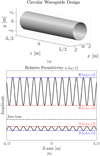 |
Fig. 1 (a) The hollow circular waveguide with radius r0 and a length L. (b) The lossy graded multilayered dielectric media occupying the hollow circular waveguide have a relative permittivity that alternates between two different dielectrics ε1 and ε2. The permeability is kept constant along the waveguide length. |
3 Numerical solutions from COMSOL and comparison to the analytical results
To validate our analytical solutions for the electric and magnetic field vectors in (10)–(14), we make a comparison to a numerical simulation of the fundamental TE11-mode in a hollow circular waveguide using the finite element method (FEM) based software COMSOL Multiphysics. The TE11-mode is utilized as the fundamental mode for validation, since it is the commonly employed operational mode in a hollow circular waveguide. Thereby, we do not need to designate a specific mode within COMSOL. In general however, it should be noted that our analytical and numerical methods can be applied to any arbitrary order TE- and TM-modes.
We chose a 3D axial-symmetric geometry to model the circular waveguide with a radius r0 = 0.1 m and a waveguide length of L = 2 m. Furthermore, we chose the COMSOL physics module “Electromagnetic Waves, Frequency Domain” (emw) since we are interested in solving for the time-harmonic electromagnetic field distribution in the microwave frequency regime. The hollow volume inside the waveguide is filled with a continuous and periodic graded multilayered dielectric composite described by functions (1) and (2). A “Perfect Electric Conductor” (PEC) boundary condition is applied to the waveguide wall, and the center of the waveguide is placed at the origin according to Figure 1. The exciting port is positioned to the left of the waveguide (z = −L/2), and the receiving port is placed on the right-hand side (z = L/2). This orientation of the ports allows for an electromagnetic wave to be excited and travel from negative z-values (the left) to positive z-values (the right). Both ports are domain-backed by “Perfectly Matched Layers” (PMLs) with a scaling factor of 1, a thickness of 2λ, and the typical wavelength form λ = c/f, where c is the speed of light in the media and f =2 GHz is the operating frequency. In addition, a “Scattering Boundary Condition” (SBC) was applied to the outward-facing sides of the PMLs to absorb internal reflections between the ports and the graded multilayered dielectric media. A “Swept Meshing” with separate “Distributions” for the PMLs and the waveguide domains was implemented. The “Distribution Type” was set to “Fixed Number Of Elements”, where the “Number Of Elements” value was adjusted to achieve mesh convergence. A TE11-mode was excited using the “Port Mode Settings”, and the complete implementation was tested in both 2D and 3D domains. We now present the numerical and analytical results of the electric field intensity E [V/m] for TE11-mode propagation inside a hollow circular waveguide filled with a graded dielectric composite. The results for the magnetic field intensity H [T] are also included for completeness, and exhibit similar behavior to that of the electric field. Note that the analytical results are obtained with the same meshing model as the numerical results, which implies that they possess the same mesh resolution, and unit cell- and lattice structure in all the figures presented below. This shared property between the two sets of results strengthens the validation of the proposed analytical method with respect to the FEM-based numerical simulation using COMSOL Multiphysics.
In Figure 2, we show the analytical and numerical results of the normalized 2D magnitude ||E(ρ, φ, z = − L/2)|| of the electric field in the cross-sectional (xy) plane inside the circular waveguide. This figure confirms the excitation of the desired TE11-mode, along with the asymptotic transverse decay of the field expressions in (10)–(12) concerning the waveguide wall.
In Figure 3, we show a comparison between real and imaginary parts of the analytical and numerical results of the normalized 1D electric field E(ρ = r0/2, φ = π/2, z) and the magnetic field H(ρ = r0/2, φ = π/2, z) in the longitudinal (yx) plane inside the circular waveguide respectively. This figure confirms the asymptotic longitudinal decay of the field expressions in (10)–(14) along the entire waveguide structure. In addition, these field expressions are seen to obtain a certain irregular periodic oscillation, which is characteristic behavior for the even and odd angular Mathieu functions {C, S} respectively. We observe that the analytical and numerical results are in perfect agreement.
In Figures 2 and 3, the transition parameter z0 = 0.05 m, the relative permittivities are ε1 = 1 − j0.1 and ε2 = 3 − j0.3, and we assume the permeability of free space. In Figures 3–6, the real and imaginary parts of each field vector will be highlighted with the colors blue and red, respectively.
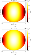 |
Fig. 2 (a) and (b) Represent the analytical and numerical results of the normalized 2D electric field magnitude ||E(ρ, φ, z = − L/2)|| [V/m] in the cross-sectional (xy) plane inside the circular waveguide. Here the transition parameter is z0 = 0.05 m, the relative permittivities ε1 = 1 − j0.1 and ε2 = 3 − j0.3, and we assume the permeability of free space. |
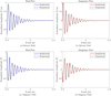 |
Fig. 3 Comparison between the analytical and numerical results for the real and imaginary part of the normalized 1D electric field intensity E(ρ = r0/2, φ = π/2, z) [V/m] and magnetic field intensity H(ρ = r0/2, φ = π/2, z) [T] in the longitudinal (yz) plane inside the circular waveguide. The subfigures (a) and (b) relate to the real and imaginary part of the normalized 1D electric field intensity E(ρ = r0/2, φ = π/2, z) [V/m], and the subfigures (c) and (d) relate to the real and imaginary part of the normalized 1D magnetic field intensity H(ρ = r0/2, φ = π/2, z) [T]. Here the transition parameter is z0 = 0.05 m, the relative permittivities are ε1 = 1 − j0.1 and ε2 = 3 − j0.3, and we assume the permeability of free space. |
3.1 Constant transition parameter with smaller losses
This section presents the results of reducing the losses of the graded multilayered dielectric media placed inside the hollow circular waveguide on the electric field intensity for the TE11-mode propagation. Figure 4 represents an analogous result to Figure 3, however, here the relative permittivities are ε1 = 1 − j0.05 and ε2 = 3 − j0.15.
In addition to the observations made from Figure 3, the characteristic behavior of the even and odd angular Mathieu functions is more pronounced for smaller losses, and the exponential decay is less noticeable in Figure 4. We also observe that the analytical and numerical results are in perfect agreement. This implies that the analytical model is valid for any degree of losses that may be included in the graded multilayered dielectric media.
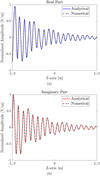 |
Fig. 4 Comparison between the analytical and numerical results for the (a) real and (b) imaginary part of the normalized 1D electric field intensity E(ρ = r0/2, φ = π/2, z) [V/m] in the longitudinal (yz) plane inside the circular waveguide. Here the transition parameter is z0 = 0.05 m, the relative permittivities are ε1 = 1 − j0.05 and ε2 = 3 − j0.15, and we assume the permeability of free space. |
3.2 Larger transition parameter with the same losses
This section studies the effects of increasing the transition parameter z0 of the graded multilayered dielectric medium inside a hollow circular waveguide on the electric field intensity for the TE11-mode propagation. Figure 5 represents an analogous result compared to Figure 3, however, here the transition parameter is z0 = 0.05 m.
In addition to the observations made in Figure 3, the characteristic behavior of the even and odd angular Mathieu functions is less pronounced for larger values of the transition parameter, and the exponential decay is more pronounced in Figure 4. Furthermore, we observe a variation in the wavelength as the wave propagates towards the center of the waveguide. This is because the graded multilayered dielectric medium occupying the hollow circular waveguide varies so slowly that the medium obtains a different permittivity at the middle of the waveguide compared to the edges. Thus, the electromagnetic wave experiences two different dielectric media and obtains different propagation velocities throughout the structure. Furthermore, we observe that the analytical and numerical results are in perfect agreement.
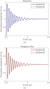 |
Fig. 5 Comparison between the analytical and numerical results for the (a) real and (b) imaginary part of the normalized 1D electric field intensity E(ρ = r0/2, φ = π/2, z) [V/m] in the longitudinal (yz) plane inside the circular waveguide. Here the transition parameter is z0 = 0.5 m, the relative permittivities are ε1 = 1 − j0.1 and ε2 = 3 − j0.3, and we assume the permeability of free space. |
3.3 Larger transition parameter with smaller losses
This section studies the effects of increasing the transition parameter and reducing the losses of the graded multilayered dielectric media placed inside a hollow circular waveguide on the electric field intensity for the TE11-mode propagation. Figure 6 presents the analogous result compared to Figure 3, however, here the relative permittivities are ε1 = 1 − j0.05 and ε2 = 3 − j0.15 and the transition parameter is z0 = 0.05 m.
In addition to the observations made from Figures 3–5, the characteristic behavior for the even and odd angular Mathieu functions {C, S} vanishes and the exponential decay is also less pronounced in Figure 6. This is a combined effect of increasing the transition parameter and reducing the losses simultaneously. In addition to the variation in the wavelength, the decay rate is also observed to decrease as the wave propagates toward the center of the waveguide. This is because the less lossy permittivity ε1 is placed about the center of the waveguide structure. This effect also occurs in Figure 5, however, it is not as pronounced there compared to the results shown in Figure 6. Furthermore, we observe that the analytical and numerical results are in perfect agreement. This implies that the analytical model is valid for any degree of transition parameter and losses in the graded multilayered dielectric media.
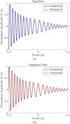 |
Fig. 6 Comparison between the analytical and numerical results for the (a) real and (b) imaginary part of the normalized 1D electric field intensity E(ρ = r0/2, φ = π/2, z) [V/m] in the longitudinal (yz) plane inside the circular waveguide. Here the transition parameter is z0 = 0.5 m, the relative permittivities are ε1 = 1 − j0.05 and ε2 = 3 − j0.15, and we assume the permeability of free space. |
4 Conclusion
We studied TE-wave propagation inside a hollow circular waveguide filled with a lossy graded multilayered dielectric composite. The dielectric composite grading and the wave propagation are directed along the z-direction. The z-dependence of the permittivity of the non-magnetic (µ = µ0) dielectric composite is modeled by a periodic sinusoidal function. The exact analytical solutions to Maxwell's equations were derived, and the obtained field solutions and wave behavior confirm the expected properties of lossy graded multilayered dielectric media inside a hollow circular waveguide. Thereafter, by means of a numerical study performed using the commercial software COMSOL Multiphysics, we show that the analytical and numerical results are in perfect agreement for all the different cases under consideration. Finally, we studied the effects of varying the transition parameter and losses of the lossy graded multilayered dielectric media, both separately and simultaneously. We observe that the analytical and numerical results are in perfect agreement for all the cases under consideration, and conclude that the analytical model is valid for any physical values of transition parameters and losses used in the graded multilayered dielectric media.
Funding
This research was funded by The Royal Institute of Technology (KTH).
Conflicts of interest
The authors have nothing to disclose.
Data availability statement
Data underlying the results presented in this paper are not publicly available at this time but may be obtained from the authors upon reasonable request.
Author contribution statement
Balwan was involved with analytical calculations and numerical verification. Mariana Dalarsson was involved with conceptualization of the study and supervision. Both authors were involved with manuscript writing.
References
- A.B. Shvartsburg, Y.A. Obod, O.D. Volpian, Chapter Six − Tunneling of electromagnetic waves in all-dielectric gradient metamaterials, Prog. Optics 60, 489 (2015), https://doi.org/10.1016/bs.po.2015.02.006 [Google Scholar]
- H. Rauh, G.I. Yampolskaya, S.V. Yampolskii, Optical transmittance of photonic structures with linearly graded dielectric constituents, New J. Phys. 12, 073033 (2010), https://doi.org/10.1088/1367-2630/12/7/073033 [CrossRef] [Google Scholar]
- W. Liu, H. Liu, X. Sun, F. Zhang, The design of large curved waveguide based on sunflower graded photonic crystal, Photonics 10, 781 (2023), https://doi.org/10.3390/photonics10070781 [Google Scholar]
- H. Giddens, Y. Hao, Multibeam graded dielectric lens antenna from multimaterial 3-D printing, IEEE Trans. Antennas Propag. 68, 6832 (2020), https://doi.org/10.1109/TAP.2020.2978949 [Google Scholar]
- S. Shukurov, C. Valagiannopoulos, Ultra-sharp angular filtering of far-field signals with graded-index multilayers, IEEE Trans. Antennas Propag. 71, 6995 (2023), https://doi.org/10.1109/TAP.2023.3281090 [Google Scholar]
- Q.L. Li, S.W. Cheung, D. Wu, T.I. Yuk, Microwave lens using periodic dielectric sheets for antenna-gain enhancement, IEEE Trans. Antennas Propag. 65, 2068 (2017), https://doi.org/10.1109/TAP.2017.2670441 [Google Scholar]
- S. Yang, O. Zetterstrom, Z. Xue, F. Mesa, O. Quevedo-Teruel, Hexagonal higher-symmetric dielectric periodic structures for planar graded-index lenses, Appl. Phys. Lett. 123, 011707 (2023), https://doi.org/10.1063/5.0150007 [Google Scholar]
- M. Pourmand, P.K. Choudhury, Wideband THz filtering by graphene-over-dielectric periodic structures with and without MgF2 defect layer, IEEE Access 8, 137385 (2020), https://doi.org/10.1109/ACCESS.2020.3012030 [Google Scholar]
- Z. Chen, B. Guo, Y. Yang, C. Cheng, Metamaterials-based enhanced energy harvesting: a review, Physica B: Condens. Matter 438, 1 (2014), https://doi.org/10.1016/j.physb.2013.12.040 [Google Scholar]
- B. Rana, B.B. Svendsen, M. Dalarsson, TEM-wave propagation in a coaxial waveguide with impedance-matched RHM to LHM transition, Optical Express 30, 32610 (2022), https://doi.org/10.1364/OE.460924 [Google Scholar]
- B. Rana, M. Dalarsson, TEM-wave propagation over an impedance-matched periodic RHM to LHM transition in a coaxial waveguide, Opt. Mater. Express 13, 1118 (2023), https://doi.org/10.1364/OME.481637 [Google Scholar]
- M. Dalarsson, S. Nordebo, TE-wave propagation in graded waveguide structures, OSA Continuum 3, 67 (2020), https://doi.org/10.1364/OSAC.379847 [Google Scholar]
- M. Dalarsson, Y. Ivanenko, S. Nordebo, Wave propagation in waveguides with graded plasmonic obstacles, J. Opt. Soc. Am. B 38, 104 (2021), https://doi.org/10.1364/JOSAB.410092 [Google Scholar]
- M. Dalarsson, Z. Jakšić, Exact analytical solution for fields in a lossy cylindrical structure with hyperbolic tangent gradient index metamaterials, Opt. Quant. Electr. 48, 209 (2016), https://doi.org/10.1007/s11082-016-0483-4 [Google Scholar]
- M. Dalarsson, General theory of wave propagation through graded interfaces between positive- and negative-refractive-index media, Phys. Rev. A 96, 043848 (2017), https://doi.org/10.1103/PhysRevA.96.043848 [Google Scholar]
- J. Xie, J. Wang, R. Ge, B. Yan, E. Liu, W. Tan, J. Liu, Multiband super-resolution imaging of graded-index photonic crystal flat lens, J. Phys. D: Appl. Phys. 51, 205103 (2018), https://doi.org/10.1088/1361-6463/aabc4a [Google Scholar]
- M. Ayik, H. Kurt, O.V. Minin, I.V. Minin, M. Turduev, Multi-directional cloak design by all-dielectric unit-cell optimized structure, Nanomaterials 12, 4194 (2022), https://doi.org/10.3390/nano12234194 [Google Scholar]
- Y. Zhu, W. Yuan, H. Sun, Y. Yu, Broadband ultra-deep sub-diffraction-limit optical focusing by metallic graded-index (MGRIN) lenses, Nanomaterials 7, 221 (2017), https://doi.org/10.3390/nano7080221 [Google Scholar]
- H. Yan, B. Fu, S. Xuan, T. Qin, X. Yao, Electromagnetic response of grading honeycomb composites for broadband microwave absorption, Compos. Struct. 321, 117280 (2023), https://doi.org/10.1016/j.compstruct.2023.117280 [Google Scholar]
- M. Abramowitz and I.A. Stegun (editors Eds.), Handbook of Mathematical Functions, with Formulas, Graphs, and Mathematical Tables, Applied Mathematics Series 55 (Dover Publications, New York, 1964), [Google Scholar]
Cite this article as: Balwan Rana, Mariana Dalarsson, TE-wave propagation in a hollow circular waveguide filled with a graded multilayered dielectric medium, EPJ Appl. Metamat. 12, 1 (2025), https://doi.org/10.1051/epjam/2025001
All Figures
|
Fig. 1 (a) The hollow circular waveguide with radius r0 and a length L. (b) The lossy graded multilayered dielectric media occupying the hollow circular waveguide have a relative permittivity that alternates between two different dielectrics ε1 and ε2. The permeability is kept constant along the waveguide length. |
| In the text | |
|
Fig. 2 (a) and (b) Represent the analytical and numerical results of the normalized 2D electric field magnitude ||E(ρ, φ, z = − L/2)|| [V/m] in the cross-sectional (xy) plane inside the circular waveguide. Here the transition parameter is z0 = 0.05 m, the relative permittivities ε1 = 1 − j0.1 and ε2 = 3 − j0.3, and we assume the permeability of free space. |
| In the text | |
|
Fig. 3 Comparison between the analytical and numerical results for the real and imaginary part of the normalized 1D electric field intensity E(ρ = r0/2, φ = π/2, z) [V/m] and magnetic field intensity H(ρ = r0/2, φ = π/2, z) [T] in the longitudinal (yz) plane inside the circular waveguide. The subfigures (a) and (b) relate to the real and imaginary part of the normalized 1D electric field intensity E(ρ = r0/2, φ = π/2, z) [V/m], and the subfigures (c) and (d) relate to the real and imaginary part of the normalized 1D magnetic field intensity H(ρ = r0/2, φ = π/2, z) [T]. Here the transition parameter is z0 = 0.05 m, the relative permittivities are ε1 = 1 − j0.1 and ε2 = 3 − j0.3, and we assume the permeability of free space. |
| In the text | |
|
Fig. 4 Comparison between the analytical and numerical results for the (a) real and (b) imaginary part of the normalized 1D electric field intensity E(ρ = r0/2, φ = π/2, z) [V/m] in the longitudinal (yz) plane inside the circular waveguide. Here the transition parameter is z0 = 0.05 m, the relative permittivities are ε1 = 1 − j0.05 and ε2 = 3 − j0.15, and we assume the permeability of free space. |
| In the text | |
|
Fig. 5 Comparison between the analytical and numerical results for the (a) real and (b) imaginary part of the normalized 1D electric field intensity E(ρ = r0/2, φ = π/2, z) [V/m] in the longitudinal (yz) plane inside the circular waveguide. Here the transition parameter is z0 = 0.5 m, the relative permittivities are ε1 = 1 − j0.1 and ε2 = 3 − j0.3, and we assume the permeability of free space. |
| In the text | |
|
Fig. 6 Comparison between the analytical and numerical results for the (a) real and (b) imaginary part of the normalized 1D electric field intensity E(ρ = r0/2, φ = π/2, z) [V/m] in the longitudinal (yz) plane inside the circular waveguide. Here the transition parameter is z0 = 0.5 m, the relative permittivities are ε1 = 1 − j0.05 and ε2 = 3 − j0.15, and we assume the permeability of free space. |
| In the text | |
Current usage metrics show cumulative count of Article Views (full-text article views including HTML views, PDF and ePub downloads, according to the available data) and Abstracts Views on Vision4Press platform.
Data correspond to usage on the plateform after 2015. The current usage metrics is available 48-96 hours after online publication and is updated daily on week days.
Initial download of the metrics may take a while.