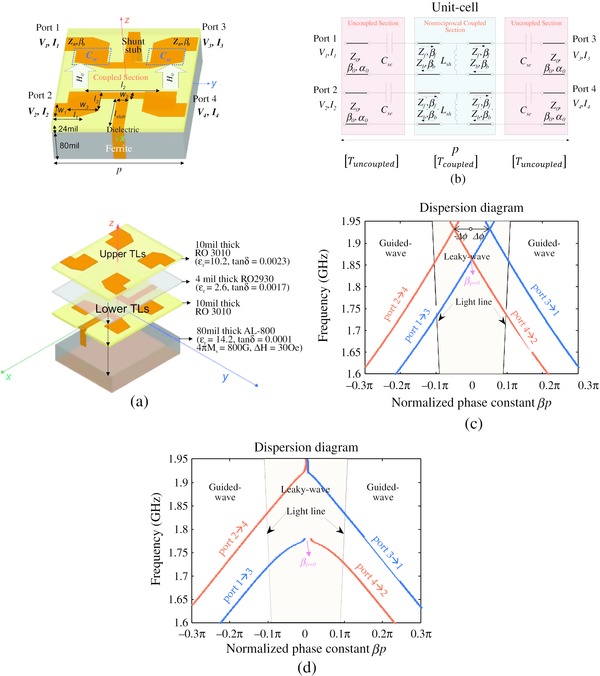
Figure 5.
Download original image
(a) Modified unit-cell geometry with series chip capacitors and shunt inductors to introduce low frequency resonance in the leaky-wave region of the K-ω diagram. This approach allowed us to miniaturize the LWA design and to operate at L-band. Dimensions are: l 1 = 105, l 2 = 120, w 1 = 60, w 2 = 30, w 3 = 80, l 3 = 75, l stub = 131.5 (mils), and (b) its equivalent circuit model as a cascade of uncoupled and coupled sections to analytically calculate the unit-cell T-matrix. (c) Dispersion curves when coupling between the lines (L m = 10−3 pH, C m = 10−3 pF) is negligible and (d) when L m = 5.45 nH, C m = 1.15 pF.
Current usage metrics show cumulative count of Article Views (full-text article views including HTML views, PDF and ePub downloads, according to the available data) and Abstracts Views on Vision4Press platform.
Data correspond to usage on the plateform after 2015. The current usage metrics is available 48-96 hours after online publication and is updated daily on week days.
Initial download of the metrics may take a while.