| Issue |
EPJ Applied Metamaterials
Volume 3, 2016
Metamaterial-by-Design: Theory, Methods, and Applications
|
|
|---|---|---|
| Article Number | 2 | |
| Number of page(s) | 8 | |
| DOI | https://doi.org/10.1051/epjam/2016003 | |
| Published online | 05 July 2016 | |
https://doi.org/10.1051/epjam/2016003
Research Article
Degenerate-band-edge engineering inspired by nonlocal transformation optics
Waves Group, Department of Engineering, University of Sannio, Corso Garibaldi 107, 82100
Benevento, Italy
* e-mail: vgaldi@unisannio.it
Received:
18
March
2016
Accepted:
30
May
2016
Published online: 5 July 2016
We address the engineering of degenerate-band-edge effects in nonlocal metamaterials. Our approach, inspired by nonlocal-transformation-optics concepts, is based on the approximation of analytically-derived nonlocal constitutive “blueprints”. We illustrate the synthesis procedure, and present and validate a possible implementation based on multilayered metamaterials featuring anisotropic constituents. We also elucidate the physical mechanisms underlying our approach and proposed configuration, and highlight the substantial differences with respect to other examples available in the topical literature.
Key words: Dispersion engineering / Optical nonlocality / Transformation optics / Degenerate band edge
© M. Moccia et al., Published by EDP Sciences, 2016
 This is an Open Access article distributed under the terms of the Creative Commons Attribution License (http://creativecommons.org/licenses/by/4.0), which permits unrestricted use, distribution, and reproduction in any medium, provided the original work is properly cited.
1 Introduction
Nonlocal light-matter interactions [1, 2] are becoming increasingly relevant in a broad variety of application scenarios including dispersion engineering [3], ultrafast nonlinear optical response [4], artificial magnetism [5], additional extraordinary waves [6], enhanced spontaneous emission [7, 8], Dirac-point conical dispersion [9], scattering suppression [10], topological transitions [11], and light-based analog signal processing [12].
In a series of recent investigations [13, 14], we have been concerned with possible extensions of the well-established transformation-optics (TO) framework [15, 16] so as to systematically engineer metamaterials exhibiting desired nonlocal effects. As opposed to the conventional TO formulation, which exploits the form-invariant properties of Helmholtz or Maxwell’s equations with respect to spatial (and, hence, inherently local) coordinate transformations, the basic idea underlying our approach is to apply the coordinate-transformation machinery in the wavevector-frequency phase-space, accessed via spatial Fourier transform. In such phase space, nonlocal effects naturally manifest themselves in terms of wavevector-dependent constitutive properties, and can be associated with nonlinear wavevector transformations. In a series of application examples, we illustrated the insightful correspondences between typical nonlocal effects and the geometrical/analytical characteristics of the associated transformations, which indicate that the powerful geometrically-driven design, typical of conventional TO, is retained by our approach, with the actual synthesis problem reduced to the suitable approximation of analytically-derived constitutive “blueprints”. For instance, we showed that (non)reciprocal effects and the appearance of additional extraordinary waves [6] are directly related to the (non-)centersymmetry and multivaluedness, respectively, of the transformations [13]. Moreover, we derived the analytical properties of classes of transformations that could induce stationary points in the dispersion diagram, and we also showed that frequency-dependent wavevector transformations enable a finer tailoring in the phase space, thereby opening up the possibility to engineer complex spatio-temporal dispersion effects such as Dirac-point conical singularities [14].
In this paper, as a further illustration of the potential of the above approach, we apply it to the engineering of degenerate band edge (DBE) effects. Such exotic dispersion effects, first studied by Figotin, and Vitebskiy [17–21], are eliciting a growing attention (see, e.g., [22–30] and references therein) in view of their potential relevance to diverse applications including slow light, solid-state lasers, quantum-cascade lasers, sensors, optical delay lines, traveling-wave tubes, distributed solid-state amplifiers, and switches. Here, inspired by our nonlocal TO approach, we investigate an alternative metamaterial-based design, which is amenable to a multilayered implementation.
Accordingly, the rest of the paper is structured as follows. In Section 2, we introduce the problem statement and our general design strategy. In Section 3, we outline the synthesis procedure, from the derivation of the ideal constitutive blueprints to the actual multilayered implementation. In Section 4, we illustrate some representative examples, and we validate them via full-wave numerical simulations, by ascertaining the emergence of typical DBE physical “footprints”. Finally, in Section 5, we draw some brief conclusions, and provide few hints for future research.
2 Problem statement and geometry
In a series of influential studies [17–21], Figotin and Vitebskiy investigated the theoretical implications of stationary points in a dispersion relationship. Assuming a time-harmonic exp(−iωt) dependence, and given a general dispersion law ω(β) relating the angular frequency ω and the propagation constant β, a ν-th order stationary point at ω = ω0 is characterized by (1)with β0 = β(ω0). This implies that, within a neighborhood of such point, the dispersion law behaves as
 (2)
(2)
The most trivial example of stationary point is the so-called regular band edge, corresponding to ν = 2 in equations (1) and (2), and naturally occurring in periodic structures such as photonic crystals. Less common and more subtle are higher-order cases such as ν = 3 and ν = 4. The former (ν = 3) is associated with the so-called “frozen-modes”, which can occur, e.g., in suitably engineered photonic crystals containing anisotropic material constituents. The latter (ν = 4) constitutes the DBE case of specific interest here, and differs fundamentally from the regular band edge case above, mainly due to the critical contribution of degenerate evanescent modes. The reader is referred to [17–21] for a thorough discussion of the theoretical details and related physical implications.
Here, we limit ourselves to emphasize that DBEs may give rise to giant slow-wave resonances which, by comparison with the regular-band-edge counterparts, tend to exhibit much larger energy accumulation and, consequently, much stronger light-matter interactions. This may lead, for instance, to giant gain enhancement [30].
DBEs can be obtained in photonic crystals containing uniaxial media with suitably tilted optical axes, as an effect of the coupling between two modes with different polarizations [17–21, 30]. Alternatively, they can also be engineered in optical fibers with multiple gratings [22, 24, 27], coupled periodic waveguides [23, 25, 26, 28], and periodically-loaded circular waveguides [29].
Here, we explore a different configuration based on a nonlocal metamaterial. As schematically illustrated in Figure 1a, we consider a 2-D scenario (with geometry and field quantities independent of y) where a transverse-magnetic-polarized plane-wave (with y-directed magnetic field) propagates in a homogeneous space entirely filled by a nonlocal, anisotropic medium. Such medium is assumed as nonmagnetic, and is characterized by a relative-permittivity tensor  which depends on the wavevector k. Here and henceforth, the tilde ~ identifies wavevector-dependent quantities.
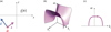 |
Figure 1. (a) Problem schematic in the assumed 2-D (x, z) reference system (with geometry and field quantities independent of y). We consider a transversely-magnetic-polarized plane-wave (with wavevector k) propagating in a homogenous space filled up by a nonlocal, nonmagnetic, anisotropic medium characterized by a relative-permittivity constitutive tensor |


By focusing on a simple uniaxial anisotropy, the arising plane-wave dispersion relationship can be simply written in terms of the relevant components ( and
and  ) as
) as (3)where kx and kz denote the x- and z-domain wavenumbers, respectively, and c is the speed of light in vacuum.
In what follows, inspired by our previously introduced nonlocal TO approach, we derive the ideal blueprints for the nonlocal medium so as to induce a DBE stationary point in the dispersion relationship (3). Moreover, we also address the synthesis of a multilayered metamaterial implementation that suitably approximates (within a neighborhood of the DBE stationary point) such ideal blueprints. Though still based on a periodic multilayer, our implementation is substantially different from those in references [17–21].
3 Synthesis procedure
3.1 Ideal constitutive blueprints
In reference [14], within the framework of nonlocal TO, we derived a class of wavevector transformations that could induce stationary points (of arbitrary order) in the dispersion relationship. In particular, we explored in detail the case ν = 3 in equations (1) and (2), corresponding to the “frozen-mode” regime. A similar approach could be applied to deal with the DBE (ν = 4) case of interest here. For brevity, we do not repeat here the analytical developments, which can be found in reference [14]. In fact, as discussed in reference [14], while providing a systematic, constructive derivation of the required material blueprints, our approach is not the only possible one, as the problem does not admit a unique solution. Moreover, for the particular 2-D, coordinate-separable and non-magnetic structure of the arising constitutive blueprints, their interpretation is rather straightforward.
Paralleling [14], we consider the following class of coordinate-separable material blueprints (henceforth identified by the superscript “BP”): (4)where εzz0 is a constant, and
  is a polynomial function. It can be readily verified, from equation (3), that
 (5)with
  denoting spectral functions. Therefore, by assuming propagation along the z-direction (i.e., kx = 0, kz = β), the desired DBE condition in equation (1) (with ν = 4) can be attained by choosing
 (6)where γ is a nonzero real constant, and k0 = ω0/c = 2π/λ0 denotes the wavenumber in vacuum at the design angular frequency (with λ0 denoting the corresponding wavelength). Moreover,
  is an arbitrary function that vanishes (together with its first four derivatives) at kz = β0,
 (7)with rm denoting arbitrary coefficients.
As anticipated, the particularly simple analytical structure of the constitutive blueprints (4) [together with Eq. (6)] makes it possible to readily verify, by simple inspection, that the desired DBE conditions are fulfilled. In particular, via straightforward algebra, the coefficient γ in equation (6) can be directly related to the nonzero derivative term in the dispersion equation [cf. Eq. (1)], (8)
(8)
Figure 1b qualitatively shows the dispersion surface [cf. Eq. (3)] pertaining to the above class of constitutive blueprints (with  ). As it can be observed, the quartic nature of the dispersion relationship gives rise to two modal branches, which degenerate at the design angular frequency, thereby yielding the sought DBE-type stationary point in the dispersion diagram, as more clearly visible in the kx = 0 cut shown in Figure 1c.
It is worth highlighting that the class of constitutive blueprints in equations (4) and (6) is idealized, and does not necessarily fulfill the physical feasibility conditions (e.g., causality) in the entire (k, ω) phase space (see also the discussion in Ref. [14]). Likewise, the dispersion characteristics in Figures 1b and 1c should only be intended as conceptual illustrations, since explicit temporal dispersion (i.e., explicit ω-dependence) is neglected.
3.2 Multilayered metamaterial synthesis
Having determined a class of ideal constitutive blueprints that yields the desired dispersion effects, as in reference [14], the synthesis problem can be formulated as finding a physical metamaterial structure whose (nonlocal) effective constitutive parameters suitably approximate the targeted blueprints. It is important to stress that, in our problem, such approximation is needed only within a limited region of the phase space, i.e., in the vicinity of the DBE stationary-point (kx = 0, kz = β0, ω = ω0). As discussed in reference [14], this generally renders the synthesis problem tractable, even though the assumed blueprints may appear as unphysical if extended to the entire phase space (see also the discussion above).
In view of the uniaxial character and analytical (rational) structure of the assumed blueprints in equations (4) and (6), multilayered metamaterials represent a particularly suited implementation. In the recent technical literature, several approaches have been proposed for the derivation of nonlocal effective models of metallo-dielectric multilayered metamaterials (see, e.g., [31–35]). Here, we utilize a generalized version of the approach proposed by Elser et al. [31], which determines the approximate nonlocal effective model in such a way the corresponding dispersion relationship matches the Taylor expansion of the exact one (around a desired phase-space point) up to a given order. First, we note that, in view of equation (6), the constitutive blueprints (4) that we need to approximate contain odd powers of kz. The implied symmetry breaking (in the z-direction) could be physically induced in various ways, e.g., by considering uniaxially-anisotropic material constituents with tilted optical axes and/or gyrotropic (nonreciprocal) materials. Here, we consider this latter case, which allows us to directly exploit the results in reference [14]. Accordingly, we consider a generic periodic multilayer, stacked along the x-direction, and with a unit-cell composed of nonmagnetic, homogeneous, isotropic or gyrotropic layers. Hence, the p-th material constituent can be generally characterized by a relative permittivity tensor![$$ {\underline{\underline{\epsilon }}}_p=\left[\begin{array}{lll}{\epsilon }_p& 0& i{\kappa }_p\\ 0& 1& 0\\ -i{\kappa }_p& 0& {\epsilon }_p\end{array}\right], $$](/articles/epjam/full_html/2016/01/epjam160002/epjam160002-eq16.gif) (9)with κp = 0 yielding the isotropic case. It can be shown (see [14] for details) that, in the vicinity of the DBE stationary-point of interest kx = 0, kz = β0, ω = ω0, the above class of metamaterials can be described in terms of the nonlocal effective parameters
(9)with κp = 0 yielding the isotropic case. It can be shown (see [14] for details) that, in the vicinity of the DBE stationary-point of interest kx = 0, kz = β0, ω = ω0, the above class of metamaterials can be described in terms of the nonlocal effective parameters (10)where d is the multilayer period (unit-cell thickness), the array
  symbolically denotes the set of geometrical and constitutive parameters of the multilayer (with the explicit dependence on ω0 and β0 omitted for notational simplicity), and the functions χl are chosen so that arising dispersion equation matches the Taylor series (about kx = 0, kz = β0, ω = ω0) of the exact one up to the second-order in kx and fourth-order in kz.
The synthesis problem can thus be cast as finding an “optimal” multilayer parameter set  , so that the nonlocal effective model (10) approximately matches the desired constitutive blueprints [cf. Eqs. (4) and (6)] in the vicinity of the DBE stationary point. To further relax the synthesis problem, we only set
  and leave as degrees of freedom the parameters γ and β0 in the blueprints, whereas, though not directly relevant in the assumed incidence conditions, the parameter εzz0 in equation (4) is obtained by simple matching at kx = 0,
 (11)
(11)
We are thus led to an optimization problem, i.e., finding the multilayer parameter set  as well as the blueprints degrees of freedom γ and β0 that minimize a suitable error functional,
![$$ {\left[{\underline{\alpha }}^{(\mathrm{opt})};{\gamma }^{(\mathrm{opt})},{\beta }_0^{\left(\mathrm{opt}\right)}\right]=\underset{\underline{\alpha },\gamma,{\beta }_0\enspace }{\mathrm{argmin}}\sum_{j=1}^J{w}_j\left|{\stackrel{\tilde }{\epsilon }}_{{xx}}^{(\mathrm{BP})}\left({k}_{{zj}};\gamma,{\beta }_0\right)-{\stackrel{\tilde }{\epsilon }}_{{xx}}^{(\mathrm{eff})}\left({k}_{{zj}};\underline{\alpha }\right)\right|}^2, $$](/articles/epjam/full_html/2016/01/epjam160002/epjam160002-eq23.gif) (12)with kzj and wj, j = 1, …, J denoting discrete kz-samples around kz = β0 and positive weight coefficients, respectively.
(12)with kzj and wj, j = 1, …, J denoting discrete kz-samples around kz = β0 and positive weight coefficients, respectively.
For the minimization of the error functional (12), we found that a combination of a standard differential-evolution algorithm and the Nelder-Meald method (see Appendix for details), while not necessarily guaranteeing the convergence to the global minimum, usually provided reasonably good results.
4 Representative results
As an illustrative example of application, we consider a multilayered metamaterial implementation with a four-layer unit-cell, containing three isotropic layers and a gyrotropic one (see the inset in Figure 2b). Since we are only interested in a very narrow frequency range (ω ≈ ω0), we neglect the material dispersion of the constituents. Moreover, for a better illustration of the phenomena, we also neglect material losses.
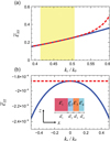 |
Figure 2. (a), (b) Effective constitutive parameters at the design angular frequency ω = ω0. Red-dashed curves represent the optimized blueprints, obtained from equations (4) and (6), with |


Figure 2 illustrates the synthesis results (in terms of nonlocal effective constitutive parameters) obtained by choosing, in the error functional (12), J = 21 kz-samples equispaced within the interval [0.9β0, 1.1β0], with uniform weights (wj = 1).
More specifically, for the optimized parameters given in the caption, Figure 2a compares the blueprint and synthesized  components, over the relevant spectral range. A fairly good agreement is observed, especially within the (yellow-shaded) range [0.9β0, 1.1β0] where the parameter matching was directly enforced. Though not directly relevant for the assumed kx = 0 propagation direction, Figure 2b shows the corresponding
  components, which are exactly matched only at kx = 0 [cf. Eq. (11)], but do not substantially differ over a reasonably wide kx-range.
From the optimized multilayer parameters given in Figure 2 caption, we note the presence of both positive and negative values of the permittivities. This is expectable, as strong nonlocal effects in multilayer configurations typically stem from the excitation and coupling of surface-plasmon polaritons (SPPs) supported at the interfaces separating the negative- and positive-permittivity layers [6–12].
For the optimized parameter configuration, Figure 3 shows the dispersion diagram for kx = 0, numerically computed via a rigorous transfer-matrix-based approach (see [14] for details), in the vicinity of the design angular frequency ω0, from which the attained DBE condition (at kz = β0 = 0.46k0) is clearly visible. Also visible is the nonreciprocal character, manifested in the center-symmetry breaking; albeit not strictly required, this is a direct consequence of our design strategy relying on a gyrotropic material constituent (see the discussion in Sect. 3). The inset shows a magnified detail around the DBE stationary point, which highlights the good local agreement with the blueprint prescription.
 |
Figure 3. Numerically-computed dispersion diagram (blue-solid curve) for the synthesized multilayered metamaterial (with parameters as in Figure 2 caption), for kx = 0 in the vicinity of the design angular frequency ω0. The inset shows a magnified view around the DBE stationary point, compared with the blueprint prediction (red-dashed curve). |
Figure 4 shows instead a few representative (numerically-computed) equi-frequency contours pertaining to the synthesized multilayered metamaterial. It can be observed that, as the angular frequency approaches the design value ω0, the equi-frequency contours tend to shrink and loose their center-symmetric character, and eventually degenerate to the DBE point.
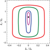 |
Figure 4. Numerically-computed equi-frequency contours for the synthesized multilayered metamaterial (with parameters as in Figure 2 caption), at angular frequencies ω = 0.9ω0, ω = 0.99ω0, ω = 0.995ω0, ω = 0.999ω0 (red, green, blue, magenta curves, respectively). At ω = ω0, the equi-frequency contour degenerates to the DBE stationary point (indicated with a black-cross marker). |
As a further, independent validation of the above synthesis, we now consider a half-space made of the synthesized multilayered metamaterial under transverse-magnetic plane-wave illumination (at the design angular frequency), normally-impinging along the positive z-direction from a vacuum half-space. Figure 5 shows a finite-element -computed (see Appendix for details) magnetic field map, over the multilayer unit-cell, which exhibits the typical physical “footprints” associated with the DBE regime [17–21]. As it can be observed, the field is transmitted (with small reflection) in the metamaterial half-space, where it gets converted into an extended mode with growing amplitude. At a distance of about ~5λ0 from the vacuum-metamaterial interface, the amplitude reaches a maximum value that is over a factor 1000 larger than the incident one, and then it starts decreasing.
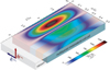 |
Figure 5. Finite-element-computed magnetic-field map, at the design angular frequency ω0, over a unit cell of the synthesized multilayered metamaterial (with parameters as in Figure 2 caption). A half-space configuration is assumed, with plane-wave excitation normally impinging from vacuum. The false-color-scale map indicates the field magnitude normalized with respect to the incident one. The field map is superimposed on the unit-cell (shown in trasparency). |
Figure 6 shows instead the magnetic energy density (normalized with respect to the incident one, and averaged across the unit cell) (13)as a function of the angular frequency, at a distance z0 = 5.25λ0 from the vacuum-metamaterial interface (where the resonant transmitted field is maximum, cf. Figure 5). As it can be observed, this quantity is strongly peaked at the design angular frequency ω0, reaching a value that is over five orders of magnitude larger that the incident one, and then rapidly decreasing to negligible values for ω > ω0 (i.e., in the bandgap). As evidenced in the magnified detail displayed in the inset, this is qualitatively consistent with the singular behavior predicted theoretically [17–21]
 (14)
(14)
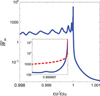 |
Figure 6. Finite-element-computed normalized magnetic density energy averaged over a unit cell [cf. Eq. (13)] of the synthesized multilayered metamaterial (with parameters as in Figure 2), at z = 5.25λ0, as a function of the angular frequency (blue solid curves). The inset shows a magnified detail around the design angular frequency, and compares it with the theoretically predicted behavior [red-dashed curve, cf. Eq. (14)]. |
The above results clearly indicate that our designed multilayered metamaterial exhibits the typical physical footprints that characterize a DBE-type giant slow-wave resonance. Within this framework, a few remarks are in order. First, though still based on a multilayered structure containing anisotropic constituents, our proposed configuration differs substantially from those in references [17–21]. By comparison with these, our configuration is 2-D, as we do not rely on modes with different polarizations. Moreover, we assume a propagation direction that is parallel, rather than orthogonal, to the layer interfaces. Accordingly, the underlying physical mechanism is also different and, in our case, it essentially exploits the strong nonlocality arising from the excitation and coupling of SPP modes at the interfaces separating the negative- and positive-permittivity layers. Finally, although the main focus of this prototype study was on a simple proof-of-concept demonstration of the phenomenology, and we did not place special emphasis on application-oriented aspects, we did make sure that the material parameters were constrained within realistic bounds. In particular, the positive relative-permittivity values considered in our synthesis range from nearly 3 to about 7, while those of the negative-permittivity and gyrotropic materials are consistent with configurations already considered in the literature (see, e.g., [9, 36]).
5 Conclusions
In conclusion, this prototype study has shown the possibility to engineer DBE-type giant slow-wave resonances by harnessing the strong nonlocal effects that can occur in multilayered metamaterials featuring positive- and negative-permittivity constituents. Starting from ideal nonlocal constitutive blueprints (inspired by our previously-developed nonlocal TO extension), we have synthesized a multilayered metamaterial that (as verified via full-wave numerical simulations) exhibited the typical DBE physical footprints.
Our results may provide an alternative route for the engineering of DBE effects, and provide further evidence of the applicability and versatility of nonlocal-TO concepts.
Current and future investigations are aimed at exploring alternative implementations, not relying on gyrotropic (nonreciprocal) materials, and/or directly exploiting the material dispersion effects. Also of great interest is the use of gain materials, for loss compensation and/or possible applications to lasing.
References
- L.D. Landau, J.S. Bell, J. Kearsley, L.P. Pitaevskii, E.M. Lifshitz, J.B. Sykes, Electrodynamics of continuous media, vol. 8, Pergamon Press, Oxford, 1984. [Google Scholar]
- V.M. Agranovich, V. Ginzburg, Crystal optics with spatial dispersion, and excitons, Springer, Berlin, 2013. [Google Scholar]
- S.M. Mikki, A.A. Kishk, in Passive microwave components and antennas, edited by V. Zhurbenko, INTECH Open Access Publisher, Rijeka, Croatia, 2010. [Google Scholar]
- G.A. Wurtz, R. Pollard, W. Hendren, G. Wiederrecht, D. Gosztola, V. Podolskiy, A.V. Zayats, Designed ultrafast optical nonlinearity in a plasmonic nanorod metamaterial enhanced by nonlocality, Nat. Nanotechnol. 6 (2011) 107–111. [CrossRef] [Google Scholar]
- A. Alù, First-principles homogenization theory for periodic metamaterials, Phys. Rev. B 84 (2011) 075153. [CrossRef] [Google Scholar]
- A.A. Orlov, P.M. Voroshilov, P.A. Belov, Y.S. Kivshar, Engineered optical nonlocality in nanostructured metamaterials, Phys. Rev. B 84 (2011) 045424. [CrossRef] [Google Scholar]
- I. Iorsh, A. Poddubny, A. Orlov, P. Belov, Y.S. Kivshar, Spontaneous emission enhancement in metal-dielectric metamaterials, Phys. Lett. A 376 (2012) 185–187. [CrossRef] [Google Scholar]
- V.A. Podolskiy, P. Ginzburg, B. Wells, A.V. Zayats, Light emission in nonlocal plasmonic metamaterials, Faraday Discuss. 178 (2015) 61–70. [CrossRef] [Google Scholar]
- L. Sun, J. Gao, X. Yang, Giant optical nonlocality near the Dirac point in metal-dielectric multilayer metamaterials, Opt. Express 21 (2013) 21542–21555. [CrossRef] [Google Scholar]
- A.S. Shalin, P. Ginzburg, A.A. Orlov, I. Iorsh, P.A. Belov, Y.S. Kivshar, A.V. Zayats, Scattering suppression from arbitrary objects in spatially dispersive layered metamaterials, Phy. Rev. B 91 (2015) 125426. [CrossRef] [Google Scholar]
- M.A. Gorlach, P.A. Belov, Effect of spatial dispersion on the topological transition in metamaterials, Phys. Rev. B 90 (2014) 115136. [CrossRef] [Google Scholar]
- A. Silva, F. Monticone, G. Castaldi, V. Galdi, A. Alù, N. Engheta, Performing mathematical operations with metamaterials, Science 343 (2014) 160–163. [CrossRef] [MathSciNet] [PubMed] [Google Scholar]
- G. Castaldi, V. Galdi, A. Alù, N. Engheta, Nonlocal transformation optics, Phys. Rev. Lett. 108 (2012) 063902. [CrossRef] [Google Scholar]
- M. Moccia, G. Castaldi, V. Galdi, A. Alù, N. Engheta, Dispersion engineering via nonlocal transformation optics, Optica 3 (2016) 179–188. [CrossRef] [Google Scholar]
- U. Leonhardt, Optical conformal mapping, Science 312 (2006) 1777–1780. [Google Scholar]
- J.B. Pendry, D. Schurig, D.R. Smith, Controlling electromagnetic fields, Science 312 (2006) 1780–1782. [CrossRef] [MathSciNet] [PubMed] [Google Scholar]
- A. Figotin, I. Vitebskiy, Oblique frozen modes in periodic layered media, Phys. Rev. E 68 (2003) 036609. [CrossRef] [Google Scholar]
- A. Figotin, I. Vitebskiy, Gigantic transmission band-edge resonance in periodic stacks of anisotropic layers, Frozen light in photonic crystals with degenerate band edge, Phys. Rev. E 72 (2005) 036619. [CrossRef] [Google Scholar]
- A. Figotin, I. Vitebskiy, Frozen light in photonic crystals with degenerate band edge, Phys. Rev. E 74 (2006) 066613. [CrossRef] [Google Scholar]
- A. Figotin, I. Vitebskiy, Slow-wave resonance in periodic stacks of anisotropic layers, Phys. Rev. A 76 (2007) 053839. [CrossRef] [Google Scholar]
- A. Figotin, I. Vitebskiy, Slow wave phenomena in photonic crystals, Laser Photonics Rev. 5 (2011) 201–213. [CrossRef] [Google Scholar]
- A.A. Sukhorukov, C.J. Handmer, C.M. de Sterke, M.J. Steel, Slow light with flat or offset band edges in few-mode fiber with two gratings, Opt. Express 15 (2007) 17954–17959. [CrossRef] [Google Scholar]
- A.A. Sukhorukov, A.V. Lavrinenko, D.N. Chigrin, D.E. Pelinovsky, Y.S. Kivshar, Slow-light dispersion in coupled periodic waveguides, J. Opt. Soc. Am. B 25 (2008) C65–C74. [CrossRef] [Google Scholar]
- N. Gutman, L.C. Botten, A.A. Sukhorukov, C.M. de Sterke, Degenerate band edges in optical fiber with multiple grating: efficient coupling to slow light, Opt. Lett. 36 (2011) 3257–3259. [CrossRef] [Google Scholar]
- N. Gutman, W.H. Dupree, Y. Sun, A.A. Sukhorukov, C.M. de Sterke, Frozen and broadband slow light in coupled periodic nanowire waveguides, Opt. Express 20 (2012) 3519–3528. [CrossRef] [Google Scholar]
- J.R. Burr, N. Gutman, C. Martijn de Sterke, I. Vitebskiy, R.M. Reano, Degenerate band edge resonances in coupled periodic silicon optical waveguides, Opt. Express 21 (2013) 8736–8745. [CrossRef] [Google Scholar]
- N. Gutman, C. Martijn de Sterke, A.A. Sukhorukov, L.C. Botten, Slow and frozen light in optical waveguides with multiple gratings: degenerate band edges and stationary inflection points, Phys. Rev. A 85 (2012) 033804. [CrossRef] [Google Scholar]
- M.G. Wood, J.R. Burr, R.M. Reano, Degenerate band edge resonances in periodic silicon ridge waveguides, Opt. Lett. 40 (2015) 2493–2496. [CrossRef] [Google Scholar]
- M.A.K. Othman, F. Capolino, Demonstration of a degenerate band edge in periodically-loaded circular waveguides, IEEE Microw. Wirel. Compon. Lett. 25 (2015) 700–702. [CrossRef] [Google Scholar]
- M.A.K. Othman, F. Yazdi, A. Figotin, F. Capolino, Giant gain enhancement in photonic crystals with a degenerate band edge, Phys. Rev. B 93 (2016) 024301. [CrossRef] [Google Scholar]
- J. Elser, V.A. Podolskiy, I. Salakhutdinov, I. Avrutsky, Nonlocal effects in effective-medium response of nanolayered metamaterials, Appl. Phys. Lett. 90 (2007) 191109. [CrossRef] [Google Scholar]
- A.V. Chebykin, A.A. Orlov, A.V. Vozianova, S.I. Maslovski, Y.S. Kivshar, P.A. Belov, Nonlocal effective medium model for multilayered metal-dielectric metamaterials, Phys. Rev. B 84 (2011) 115438. [CrossRef] [Google Scholar]
- A.V. Chebykin, A.A. Orlov, C.R. Simovski, Y.S. Kivshar, P.A. Belov, Nonlocal effective parameters of multilayered metal-dielectric metamaterials, Phys. Rev. B 86 (2012) 115420. [CrossRef] [Google Scholar]
- R.-L. Chern, Spatial dispersion and nonlocal effective permittivity for periodic layered metamaterials, Opt. Express 21 (2013) 16514–16527. [CrossRef] [Google Scholar]
- L. Sun, Z. Li, T.S. Luk, X. Yang, J. Gao, Nonlocal effective medium analysis in symmetric metal-dielectric multilayer metamaterials, Phys. Rev. B 91 (2015) 195147. [CrossRef] [Google Scholar]
- X. Lin, Y. Xu, B. Zhang, R. Hao, H. Chen, E. Li, Unidirectional surface plasmons in nonreciprocal graphene, New J. Phys. 15 (2013) 113003. [CrossRef] [Google Scholar]
- SciPy Reference Guide, available at http://docs.scipy.org/doc/scipy/reference/ [Google Scholar]
- COMSOL Group, COMSOL Multiphysics: Version 5.1, COMSOL, Stockholm, 2015. [Google Scholar]
Appendix
Details on the synthesis and numerical simulations
The minimization of the error functional in equation (12) was carried out by means of a Python-based implementation of the differential-evolution optimization algorithm available in the SciPy optimization library [37]. More specifically, we considered a population size of 100 elements (with random initialization), the “best1bin” strategy, a dithering of the mutation constant within the interval (0.5, 1), and a recombination constant equal to 0.6. We also found that slight improvements could be obtained by “polishing” the best element of the final population via the Nelder-Meald method. With reference to the specific example presented, the constitutive parameters of layer #2 (gyrotropic medium) were fixed to values already utilized in the literature [36]; for the remaining layers, the relative permittivities were assumed to vary with the realistic ranges 1 ≤ ε1,3 ≤ 11 and −10 ≤ ε4 ≤ −0.1. For the layer thicknesses, a variation range 0 < dk ≤ 0.3λ0, k = 1, …, 4 was assumed. Moreover, to avoid propagation of higher-order Bragg modes, the constraint d < λ0/2 was enforced for the total unit-cell thickness; this was implemented by adding a penalty term in the error functional (12) (equal to 100 if the constraint was not satisfied, and zero otherwise). For the remaining two optimization parameters β0 and γ, the variation ranges −2k0 ≤ β0 ≤ 2k0 and  were set.
The field map (Figure 5) and magnetic energy density (Figure 6) were computed by means of the finite-element-based commercial software package COMSOL Multiphysics [38]. More specifically, a single unit-cell was considered, extending 10λ0 along the z-direction and terminated by periodic boundary conditions along x. The structure was excited by a plane wave impinging from a 2λ0-long section of vacuum. In order to simulate a semi-infinite structure, the other side was terminated by a 60λ0-long lossy section (not shown in Figure 5) with a linearly-increasing loss profile. The structure was discretized with a maximum mesh size of λ0/100 (resulting into about 6.3 million degrees of freedom), and the MUMPS direct solver (with default parameters) was utilized.
Cite this article as: Moccia M, Castaldi G & Galdi V: Degenerate-band-edge engineering inspired by nonlocal transformation optics. EPJ Appl. Metamat. 2016, 3, 2.
All Figures
|
Figure 1. (a) Problem schematic in the assumed 2-D (x, z) reference system (with geometry and field quantities independent of y). We consider a transversely-magnetic-polarized plane-wave (with wavevector k) propagating in a homogenous space filled up by a nonlocal, nonmagnetic, anisotropic medium characterized by a relative-permittivity constitutive tensor |
| In the text | |
|
Figure 2. (a), (b) Effective constitutive parameters at the design angular frequency ω = ω0. Red-dashed curves represent the optimized blueprints, obtained from equations (4) and (6), with |
| In the text | |
|
Figure 3. Numerically-computed dispersion diagram (blue-solid curve) for the synthesized multilayered metamaterial (with parameters as in Figure 2 caption), for kx = 0 in the vicinity of the design angular frequency ω0. The inset shows a magnified view around the DBE stationary point, compared with the blueprint prediction (red-dashed curve). |
| In the text | |
|
Figure 4. Numerically-computed equi-frequency contours for the synthesized multilayered metamaterial (with parameters as in Figure 2 caption), at angular frequencies ω = 0.9ω0, ω = 0.99ω0, ω = 0.995ω0, ω = 0.999ω0 (red, green, blue, magenta curves, respectively). At ω = ω0, the equi-frequency contour degenerates to the DBE stationary point (indicated with a black-cross marker). |
| In the text | |
|
Figure 5. Finite-element-computed magnetic-field map, at the design angular frequency ω0, over a unit cell of the synthesized multilayered metamaterial (with parameters as in Figure 2 caption). A half-space configuration is assumed, with plane-wave excitation normally impinging from vacuum. The false-color-scale map indicates the field magnitude normalized with respect to the incident one. The field map is superimposed on the unit-cell (shown in trasparency). |
| In the text | |
|
Figure 6. Finite-element-computed normalized magnetic density energy averaged over a unit cell [cf. Eq. (13)] of the synthesized multilayered metamaterial (with parameters as in Figure 2), at z = 5.25λ0, as a function of the angular frequency (blue solid curves). The inset shows a magnified detail around the design angular frequency, and compares it with the theoretically predicted behavior [red-dashed curve, cf. Eq. (14)]. |
| In the text | |
Current usage metrics show cumulative count of Article Views (full-text article views including HTML views, PDF and ePub downloads, according to the available data) and Abstracts Views on Vision4Press platform.
Data correspond to usage on the plateform after 2015. The current usage metrics is available 48-96 hours after online publication and is updated daily on week days.
Initial download of the metrics may take a while.